An amplifier for every use
Amplifiers come in an abundancy of shapes and forms, and target a variety of applications. In the lab, you are likely going to need a mix of general purpose and specialized amplifiers to solve your measurement challenges. Equally important, you may want to stick to amplifiers you know well, and that are thoroughly characterized. In the following I show a few of the amplifiers I have, either salvaged from closedowns or purchased from auctions.
|
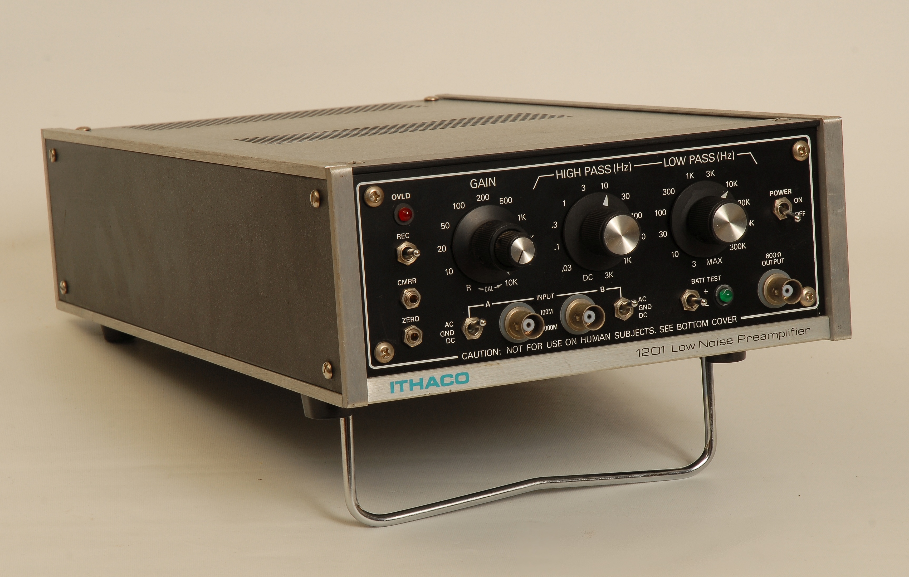
Ithaco 1201 Low Noise Preamplifier
This amplifier is by no means brand new, but it's still being manufactured and sold by DL Instruments. With its useful high-impedance, switchable balanced/unbalanced input and selectable hi/low cut-off frequencies it serves as a general purpose amplifier for low-level signals. The 1201 is spotted too rarely on the used market, unfortunately. If you get an old second-hand model expect that the NiCd cells are dead, and should be removed. If you really want to remove ground loops, however, the battery power feature is a nice feature, and then there's no way round purchasing 20 new 1.2 V NiCd cells. If the DC offset of your 1201 varies much, and if the offset trimmer on the front panel does not really help, you should take a look at the high-impedance input node of the second amplifier stage. This node is extremely sensitive to leakage currents, at least in my version of the 1201. The trace that connects the gate to the preceeding filter runs close (and totally unguarded) to other traces carrying rail voltages and anything in between. As a result, even small changes in humidity result in a changing DC-offset. As a remedy, I removed the sensitive trace in the PCB and connected the gate to the preceeding filter by a separate wire. Further details are found under the repair pages. |
|
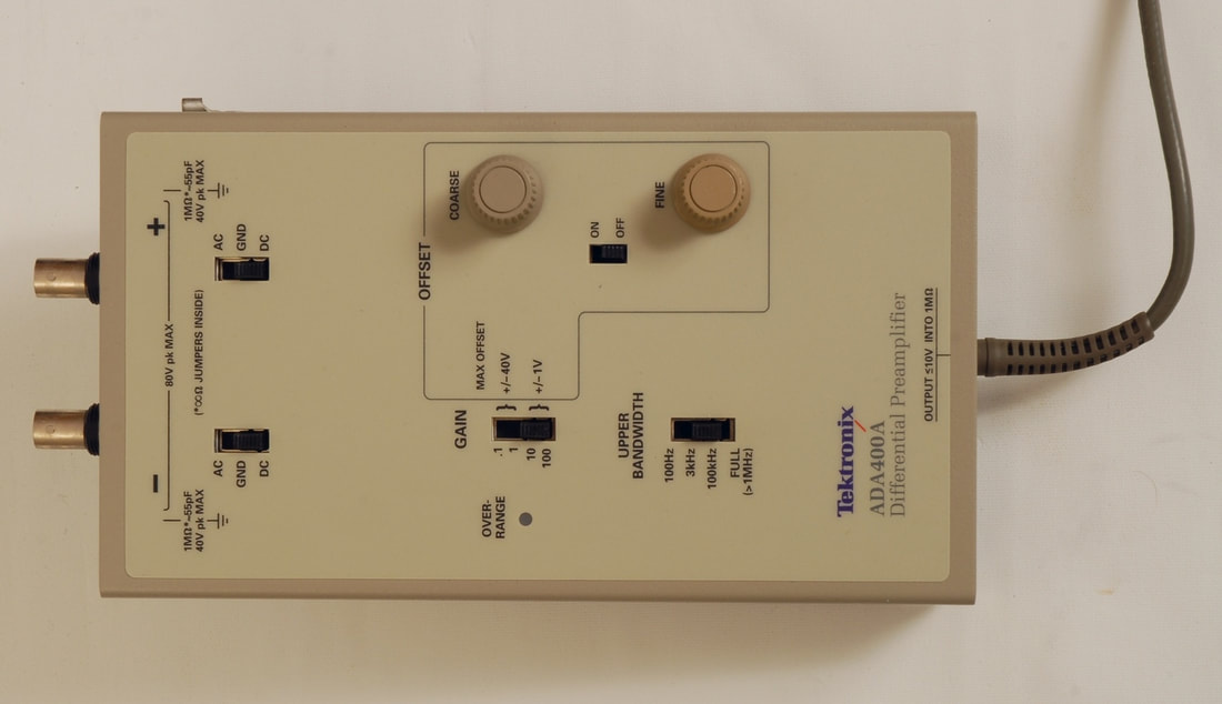
Tektronix ADA400A Differential Amplifier
The ADA400A is sort of a hybrid between a traditional differential probe and a pre-amplifier. It's powered by a Tektronix oscilloscope, or via the Tektronix 1103 Tekprobe power supply. I would recommend to get the 1103 so that you may use the ADA400A together with oscilloscopes without the Tekprobe, and with other kinds of test gear, such as a signal analyzer or an acquisition module. |
|
Picture to be added
|
Hewlett Packard 461A Amplifier
Another oldtimer, but with its 1 kHz - 150 MHz range it's still useful as a general purpose wideband amplifier. Mind you that the gain selector switch may be a bit quirky and requires attention. The 461A is often seen on the used market, but some units may be quite old and require the old HP power cord. |
|
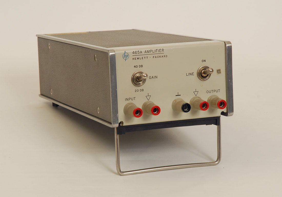
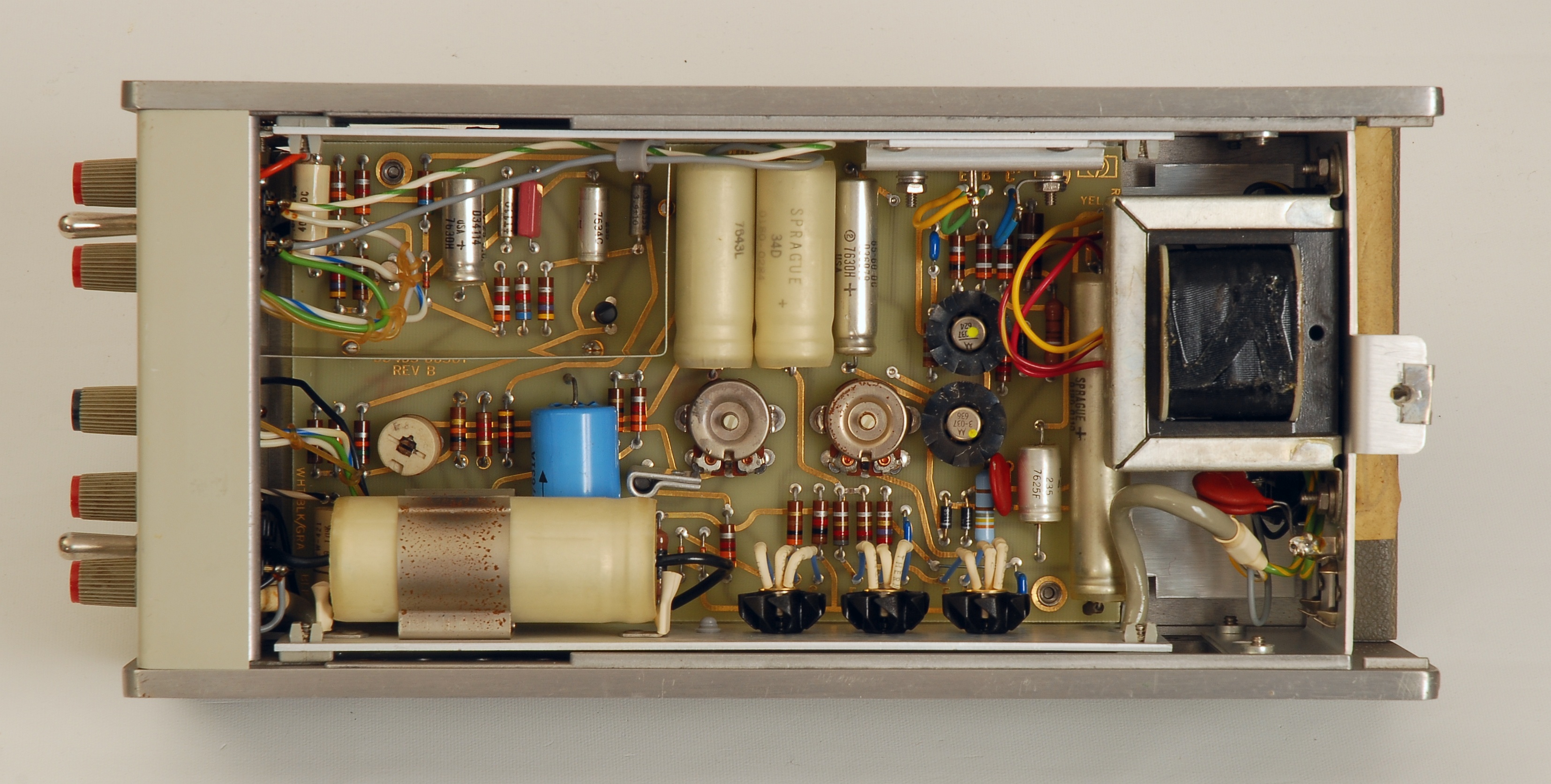
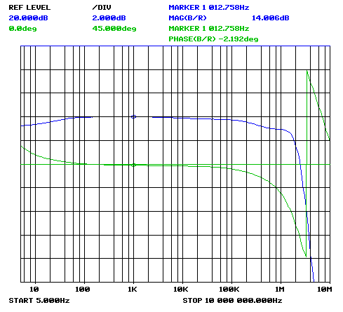
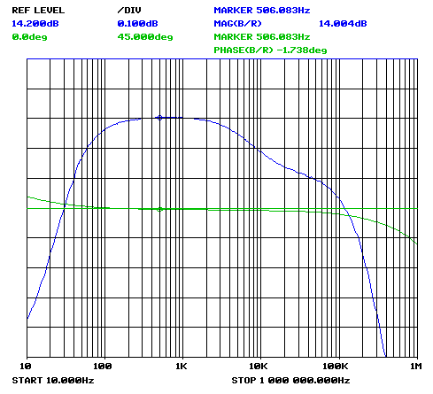
Hewlett Packard 465A Amplifier
For lower frequencies, from 5 Hz through 1 MHz, the 465A provides a convenient and switchable 20 or 40 dB gain. Granted, this is an old design from the 60's, but the form factor is convenient and the build is, as always, very nice. The model shown here, with seriel number prefix 0970A, features IEC power inlet and light grey banana plugs. The figure below shows the frequency and phase response at 40 dB gain setting, and in 50 Ohms load via a 20 dB attenuator. The sweep reveals a -3 dB cut-off at about 2 MHz, more than the specified 1 MHz. With a marker stating 14.006 dB, the unloaded gain is close to the specified 40 dB, when compensating for the load and the attenuator. The frequency response stays within +/- 0.1 dB between 40 Hz and 40 kHz; this 465A could do with a slight tuning of the high-frequency response, but I decided to postpone any tuning until the next time I service the 465A and perhaps replace the electrolytic capacitors.
|
|
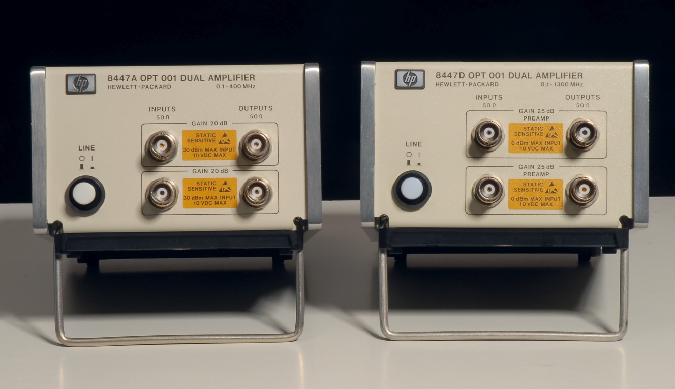
Hewlett Packard 8447A and 8447D amplifiers
The 8447A, a fixed gain amplifier with a 0.1 - 400 MHz frequency range, has served well in various of my RF setups. In the same series, the 8447D offers a wider frequency range up to 1.3 GHz, though at the cost of a slightly worse noise factor. Members of the 8447 family are often seen on the used market, unfortunately at high prices, which only reflects the amplifiers' popularity. Both units shown here are one of the later models (serial number prefix 2944A) with option 001, dual channel with BNC connectors. Note the huge difference between the specified maximum input power for the two models, +30 dBm for the 8447A, but merely 0 dBm for the 8447D. |
|
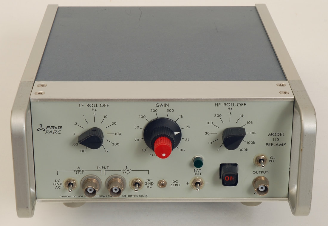
EG&G Model 113 pre-Amp
Another high-gain, low-noise laboratory amplifier, sold under the Princeton Applied Research (PAR) and the EG&G PARC brands, and with CMR adjustment on the front panel on some PAR models. EG&G purchased Princeton Applied Research in 1977, so one may assume that the older models are labeled Princeton Applied Research. The late versions of the amplifier have a more greyish colour, and the font size of the front panel artwork is slightly larger. In addition, there seems to be a typo for the overload recovery toggle switch: In the late version the text has changed from "OL REC" to "OL REG". As always, with this kind of amplifier, there's a risk of leaking NiCd cells and corroded components. For one brave attempt to clean up a messy 113 with vinegar (!), take a look at https://www.eevblog.com/forum/repair/egg-parc-model-113-preamplifier-repairrestoration/ Note that the NiCd cells in the 113 take care of the power rail stabilization, so you need a fresh set of cells, or to add linear regulators, if you remove the old cells. |
|
Stanford Research SR530 Dual Phase Lock-in Amplifier
This is one of the classic lock-in amplifiers you still get to see in many physics laboratories, and it is still (in 2022) being marketed by SRS along with its single phase version, the SR510. If you are not familiar with lock-in amplifiers and their applications, check out some of the references on the Internet, such as the SRS Tech Note "Lock-In Basics". The SR510/SR530 feature downconversion with a sine wave, which suppresses conversion of signal components at the harmonics of the reference frequency. This relaxes the requirements for pre-filtering, a great advantage in everyday's work. Still, the SR510/SR530 allows you to switch in a tracking band pass filter to suppress out-of-band noise and to avoid overload at high amplification. An important parameter of any lock-in amplifier is the dynamic reserve. This figure represents the ratio between the largest allowed interfering signal and the full-scale input voltage. The dynamic reserve depends on the actual settings, and for the SR530 it varies between 20 dB and 60 dB. By enabling the tracking band pass filter, the dynamic reserve will be increased with 20 dB. In any case, the proper use of a lock-in amplifier requires that you give the dynamic reserve some consideration and find out if you have (potential) interferers that the amplifier will be able to handle. |
|
Picture to be added
|
Stanford Research SR550 Pre-Amplifier
The SR550 is a high-impedance differential FET-input amplifier with a gain of 1x, 2x, 5x or 10x, controllable through the 9-pin sub-D interface, intended for the company's lock-in amplifiers, such as the SR530 above. The SR550 also serves as a general-purpose amplifier by applying external power (+20 V, -20 V and +5 V), having a default gain of x10. The on-board voltage regulators are of the 78L15 and 79L15 types, so it should be safe to use a +18 V / -18 V supply. If you consider using batteries for power, keep in mind the current draw of the SR550, about 38 mA and 32 mA for the +/- 20 V inputs, and that the SR550 also requires a +5 V supply. Finally, there's no polarity protection, so be careful when wiring the SR550 for external power. Note that the output B is no output at all, as there's ground on the center pin. The idea is that the differential input stage of the lock-in may suppress common-mode noise when its input B is connected to the "output B". |
|
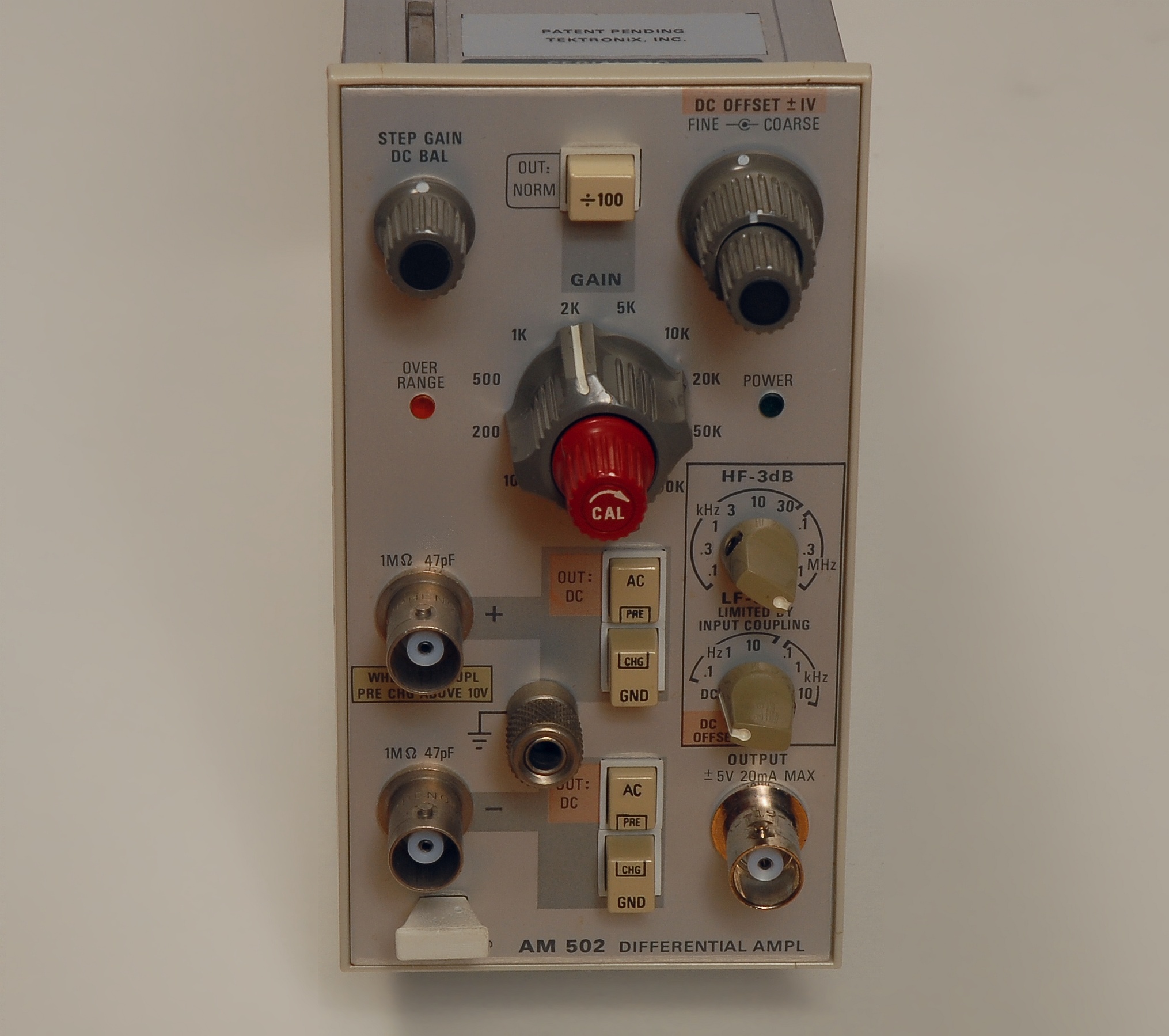
Tektronix AM502 Differential Amplifier
This is a plug-in module for the TM500 series, introduced in 1974 according to Tekwiki (http://w140.com/tekwiki/wiki/AM502). The schematics appear to have undergone a few revisions until 1986. The amplifier stages are built with discrete components entirely, and the designers have gone through a great deal of effort to obtain the specified CMRR of 100 dB up to 50 kHz. The noise of 6 nV/rtHz is close to that of the Ithaco 1201 and the EG&G 113. The AM502 has an immense maximum gain of 100k, 10x as much as the Ithaco 1201 or the EG&G 113. Note how the unit here is in pristine condition, hardly with any scratches, and with the plastic frame intact. The graph of the left shows the CMRR as a function of the frequency, measured without input attenuation, and a gain of 10k. (Graph to be added) |
|
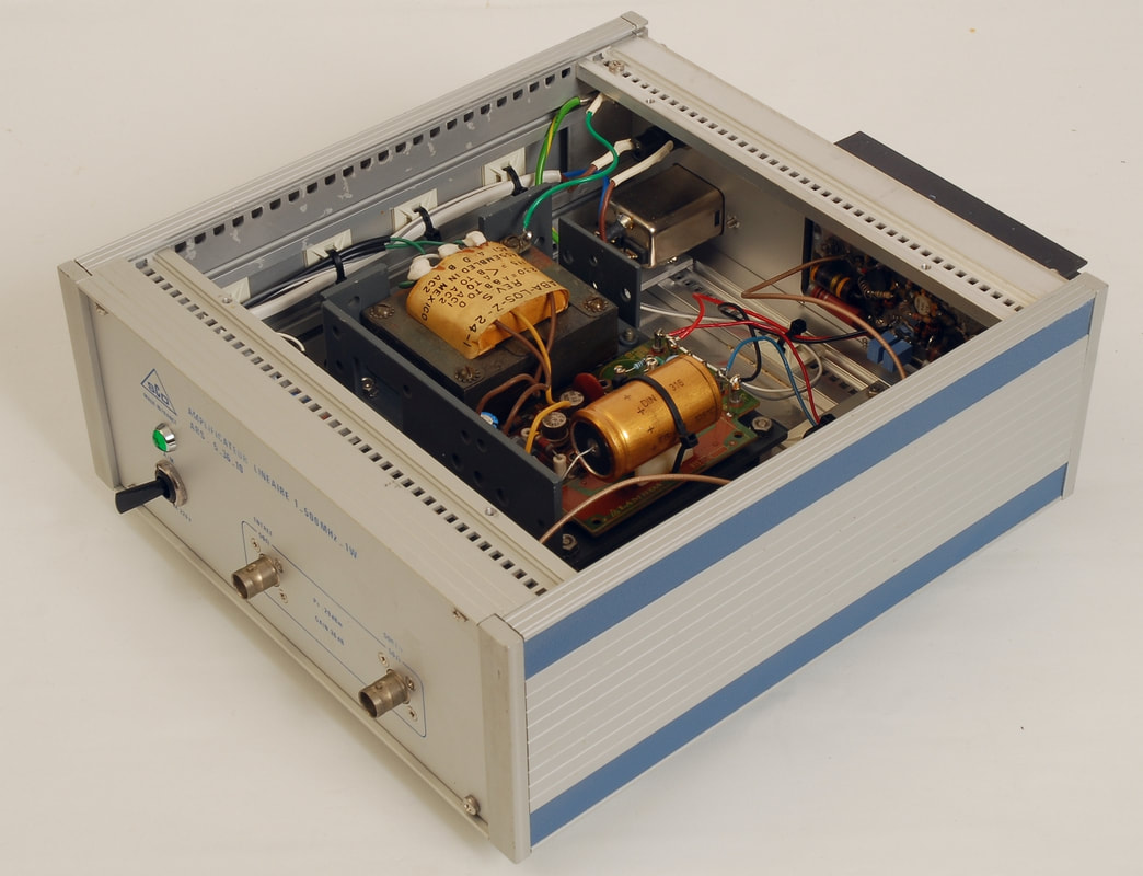
SCD Amplificateur Lineaire ARS 5_36_10
For more RF power, an amplifier such as the ARS 5_36_10 comes handy. It covers 1 - 500 MHz, up to +29 dBm, enough to drive a number of high-level mixers through a power splitter, for instance. I upgraded the amplifier with a proper IEC power inlet, and I replaced the mains switch and the electrolytic capacitors of the power supply. Finally, in order to improve the robustness and the wiring I relocated the power supply. |
|
|
DIY general purpose low-noise FET amplifier
For general amplification where low noise is a concern I designed this amplifier with a JFET in the first stage. The amplifier targets AC amplification only, and is powered from a single supply. Depending on the requirements and specific trade-offs, such as bandwidth vs. current comsumption, I populate the printed circuit board with different components. The graphs show examples of the noise density vs. frequency for two different component selections, one using the Toshiba 2SK117GR, and another using the InterFET IF9030. With the 2SK117GR the noise density reaches a respectable value of 1.67 nV/√Hz. However, with the low-noise FETs from InterFET, such as the IF9030, you move into another league. The amplifier here provides an impressive value of merely 0.66 nV/√Hz, slightly above the typical 0.5 nV√Hz at 1 kHz specified by InterFET, but still 10 times lower than the EG&G 113. Need lower noise still? Try out the InterFET IF3601 which has a specified typical noise density of just 0.3 nV√Hz at 100 Hz, and available from Mouser for just around 22 Euros for one (!), at least the last time I checked... |
|
The bandwidth of the 1211 depends on the amplification setting; In this graph, showing the response from the input to the X1 output, all gains have been normalized to 0 dB to ease the comparison.
(Graph to be added) |
Ithaco 1211 Current Preamplifier
The correct term for the 1211 and similar current amplifiers would be a transimpedance preamplifier, as it outputs a voltage, not a current. Typical uses are physics (photodetector amplification), research into semiconductors and other materials, biotech, among other fields. As any other current amplifier the bandwidth starts to decrease rapidly as gain increases, as can be seen on the graph on the left where all gains have been normalized to ease comparison of the bandwidth. The 1211 is a fine current amplifier for the lab, and is still manufactured by DL Instruments. However, if you need wider bandwidth and lower noise, you need to turn to more recent designs, such as the Keithley 428 or the models from Femto. When I got the 1211 the output was stuck at the positive rail voltage. It turned out that the first amplifier stage was working properly, so a signal was available on the direct (X1) output on the back. The filter stage merely had to be switched into the 6 dB/oct. position (by flipping the internal switch) to get a proper DC-level for all filter settings but the minimum rise time setting. Anyway, for any application using a digitizer or a lock-in amplifier I will use the direct X1 output, so the filter stage will only undergo a repair session when a need arises. |
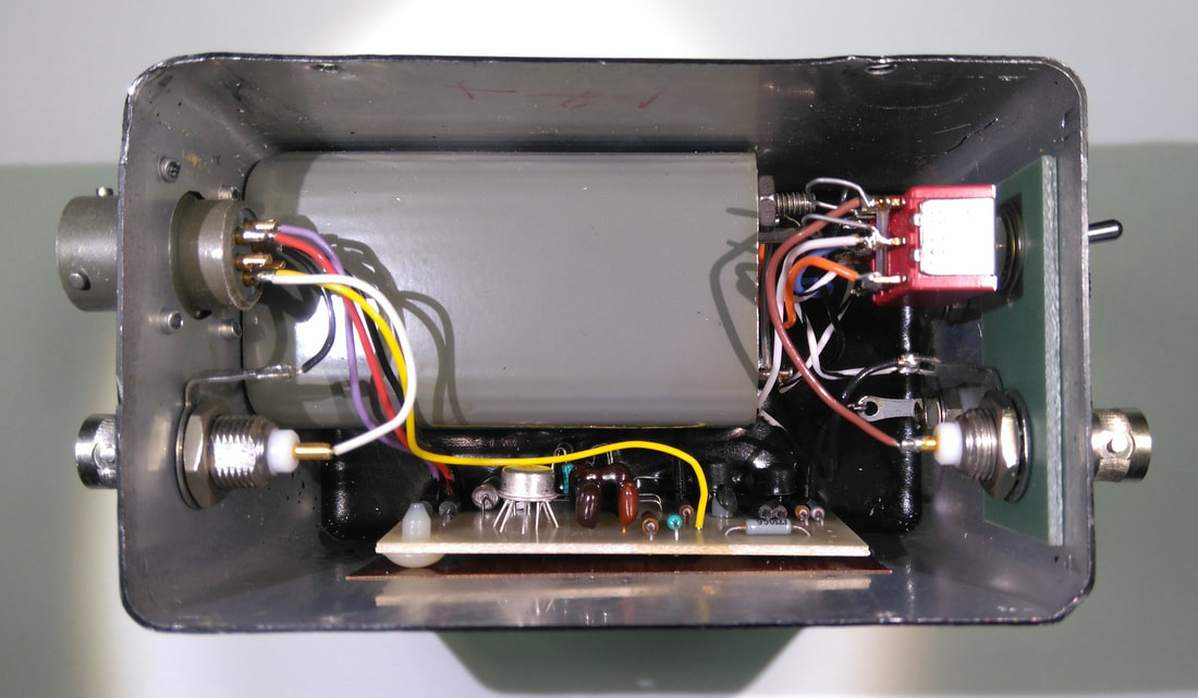
The inner parts of the Ithaco 165 preamplifier. Note the black compound in the bottom of the enclosure.
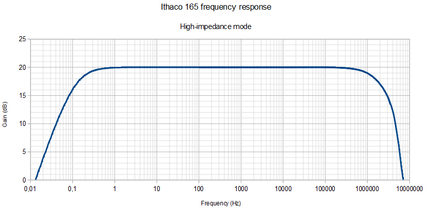
Frequency response for the high-impedance mode of the Ithaco model 165 preamplifier. The sweep is made from two separate sweeps, one using the NI USB-4431, the other the HP 3577B network analyzer, in order to span the range from 0.01 Hz to 10 MHz. The useful frequency ranges spans 1 Hz through 100 kHz and fits nicely common lock-in amplifiers.
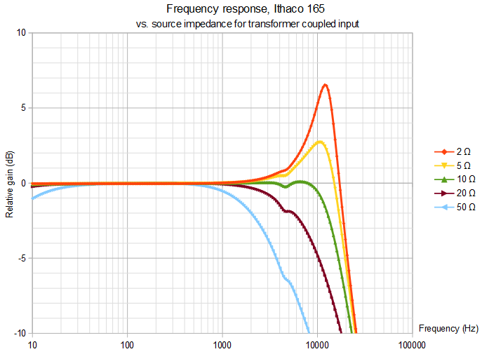
The relative gain in the low-impedance 60 dB gain mode of the Ithaco 165 for different source impedances. All 5 responses were normalized over the 100 Hz to 200 Hz range to allow comparison.
|
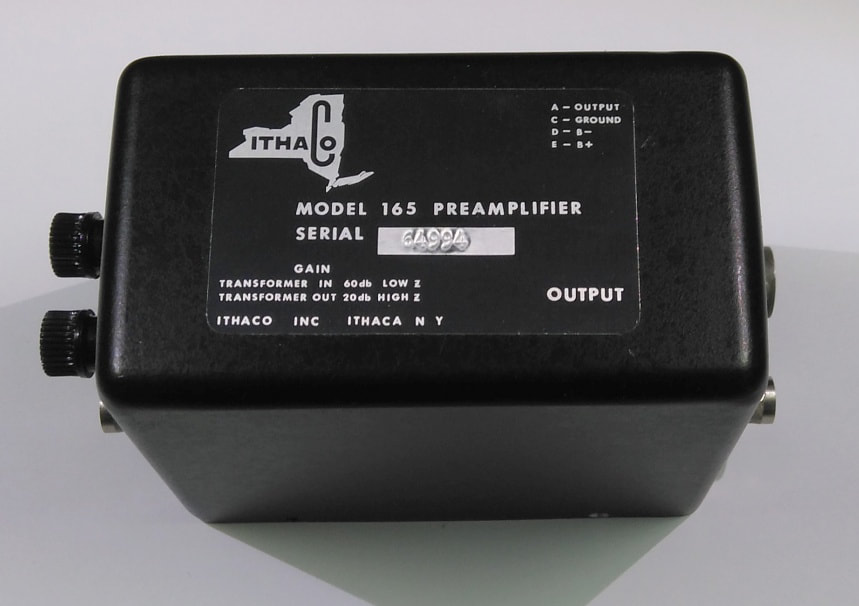
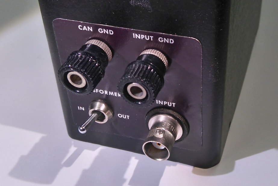
Ithaco Model 165 Preamplifier
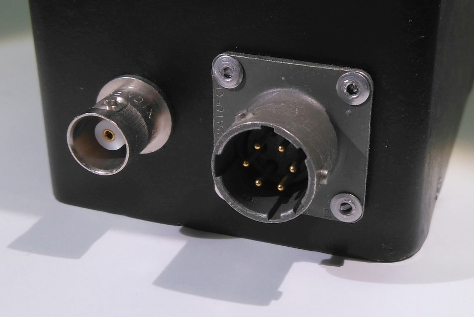
Here's a rare piece of equipment: The model 165 from Ithaco, dedicated for use with the lock-in amplifiers of the era from the company, such as the model 391 Dynatrac. The peculiar feature of the 165 is that it allows the user to switch between a high-impedance 20 dB gain mode, and a transformer-coupled low-impedance 60 dB gain mode. In the low-impedance mode the BNC input is isolated from the case and output ground, and the ground of the BNC input connector is only connected to the signal ground terminal, not the case ground terminal. It is important to note, however, that I measured the capacitive coupling between the case and signal grounds through the transformer to 420 pF, which may be an issue in a measurement setup. Mind you that the frequency response, when the transformer is being inserted in the low-impedance mode, depends heavily on the source impedance, as shown on the graph in the left column. The optimal source impedance seems to be around 10 Ω. In any case, the useful frequency range in the low-impedance mode appears to be restricted to about 50 Hz - 500 Hz, which is very narrow compared to the frequency range in the high-impedance mode. Ithaco intended to power the 165 from the lock-in amplifier through the model 391V1 cable. For those that come across the 165 and would like to put it into use, the 6-pin power connector on the 165 is an ITT/Cannon KPT02A10-6P which mates to plug KPT06F10-6S, available from RS, stock no. 466-624. Power from the 191 is +/- 16 V, but I use +/- 15 V equally well. Both the transformer and the circuit board are immersed into a black compound which will challenge any debugging and repair. As far as I can see without removing the board, the design seems to be based on a dual FET in the input in combination with an LM301. The FET is totally covered with the black compound so the make and model remain unknown. When I received the 165, it turned out that the input switch did not make contact in the high-impedance mode. Luckily, I did not have to replace the switch, but I could simply connect an unused contact in parallel with the defective contact. Ithaco had assembled the box with rivets, which I had to replace with screws. |
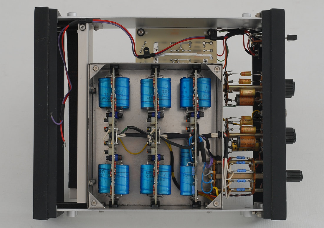
The inside of the 9431: The input stages in parallel are spread over 3 boards.
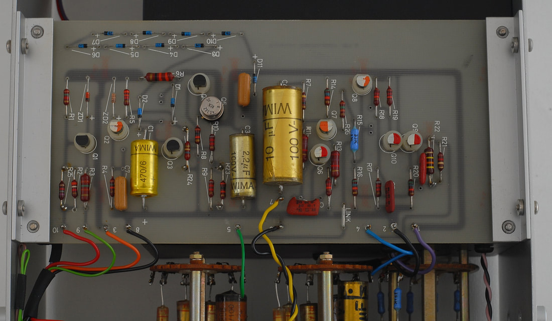
The bottom board contains the -15 V power supply, the summing amplifier and the output stage.
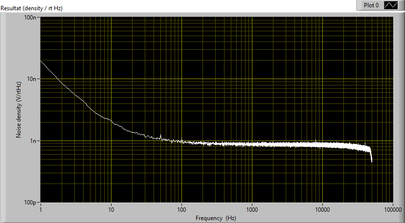
Above: Noise voltage density for the the "NORMAL" (top graph) and the "EXTRA LOW Rs" (bottom graph) impedance settings for a shorted input. Measured with NI USB-4431 using an FFT with 1 Hz bin size, and with an EG&G model 113 inserted between the Ortec Brookdeal 9431 and the USB-4431 digitizer.
Note: The graph does not represent an original unit as the original 2N4126 input transistors were all replaced with ZTX790A. |
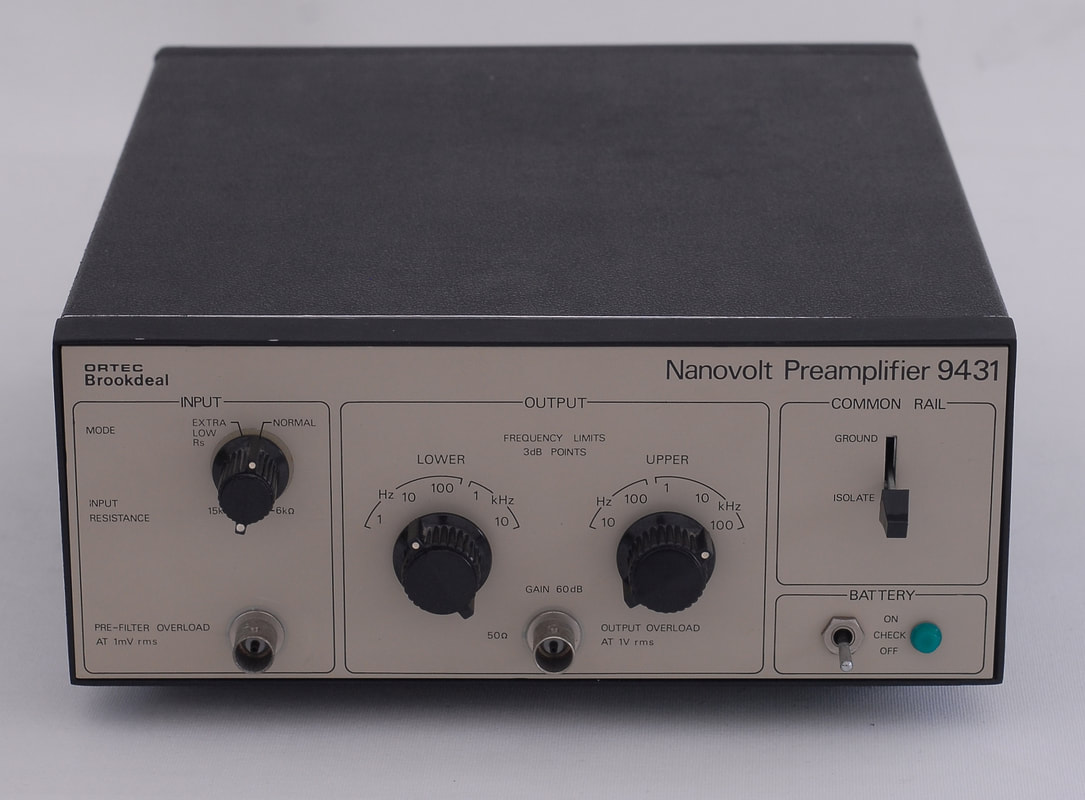
Ortec Brookdeal nanovolt amplifier 9431
The 9431 is an example of an amplifier which targets low-level physical experiments, like cryogenics. There's not really any information available on the unit, so I decided to make a short teardown and measure a few a parameters. The 9431 is seen once in a while on the surplus market, so with the description presented here you may see if the 9431 could be of interest. The gain is fixed 60 dB, and the amplifier does not amplify DC, which at first may appear as a drawback, but in many low-level applications one needs to avoid DC being amplified. In order to achieve the nice noise specifications the amplifier has a number of input amplifier stages in parallel. In the "NORMAL" mode, one stage with four 2N4126 in parallel is active. In the "EXTRA LOW Rs" mode four more stages are put in parallel in order to lower the input noise and adapt the amplifier to sources with an even lower impedance. For the sake of signal integrity, the amplifier is battery powered, but should this become an item of dissatisfaction, you may add a DC-connector to allow powering from an external supply. Note that the voltage of the four series connected 9 V size PP7 batteries normally installed in the 9431 is reduced to 15 V by the series regulator, so there's a lot of loss taking place. The green lamp goes off at about 20 V, and a 24 V supply is more than adequate. No need whatsoever for a 36 V supply! On the picture on the left the contacts for the PP7 batteries have been removed, and the purple and red wires are waiting to be connected to three rechargeable 9 V batteries and a DC-connector for charging and prolonged use. If a high isolation is required for long periods of time, and if an external supply does not offer the required isolation, you may always add an optical power isolator. When I received the 9431 the "EXTRA LOW Rs" mode was extremely noisy, and it turned out that one input stage was to blame; A clear example of the single rotten apple that spoiled the barrel. I replaced the four 2N4126 transistors of this stage with four ZTX790A , which not only fixed the stage, the noise level was now even lower than the other stages with 2N4126. In view of this I decided to replace all input transistors. The lower graphs on the left show the input-referred noise density for the two input impedance settings "NORMAL" and "EXTRA LOW Rs" with all of the 2N4126 transistors replaced with ZTX790A. The graphs were made with an EG&G amplifier set to 100 x gain inserted between the output of the 9431 and the USB-4431 to lower the noise floor. The measured noise density at shorted input: NORMAL mode: 0.982 nV/√Hz @ 100 Hz, and 0.864 nV/√Hz @1 kHz EXTRA LOW Rs mode: 0.541 nV/√Hz @ 100 Hz, and 0.403 nV/√Hz @ 1 kHz. Note, by the way, how the improvement in the noise density is close to a factor of √5 around 1 kHz, but is reduced to almost nothing at low frequencies. During the process of replacing the input transistors I learned that the output buffer stage operates at a very low bias current, about 50 µA and 150 µA collector current in the final two transistors. This is quite low and may pose an issue when driving anything else than high-impedance loads. Also, the output buffer stage was prone to oscillations. I replace the output buffer's NPN input transistor with a JFET and increased the current to 280 µA. The collector current in the PNP output transistor was increased to 1.35 mA. This is still low compared to the overall consumption (about 6.8 mA in the "NORMAL" mode, and 20 mA in the "EXTRA LOW Rs" mode). The compensation capacitor (not present in the schematics of the slightly older Brookdeal 431, but is included on the board containing the the output buffer in the Ortec Brookdeal 9431) was increased from 1.5 pF to 47 pF. BTW: Should you wonder about the brand "Ortec Brookdeal", better check out the explanation at https://www.ameteksi.com/brands/signal-recovery |
|
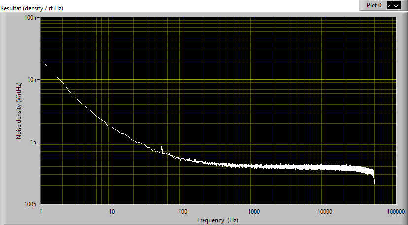
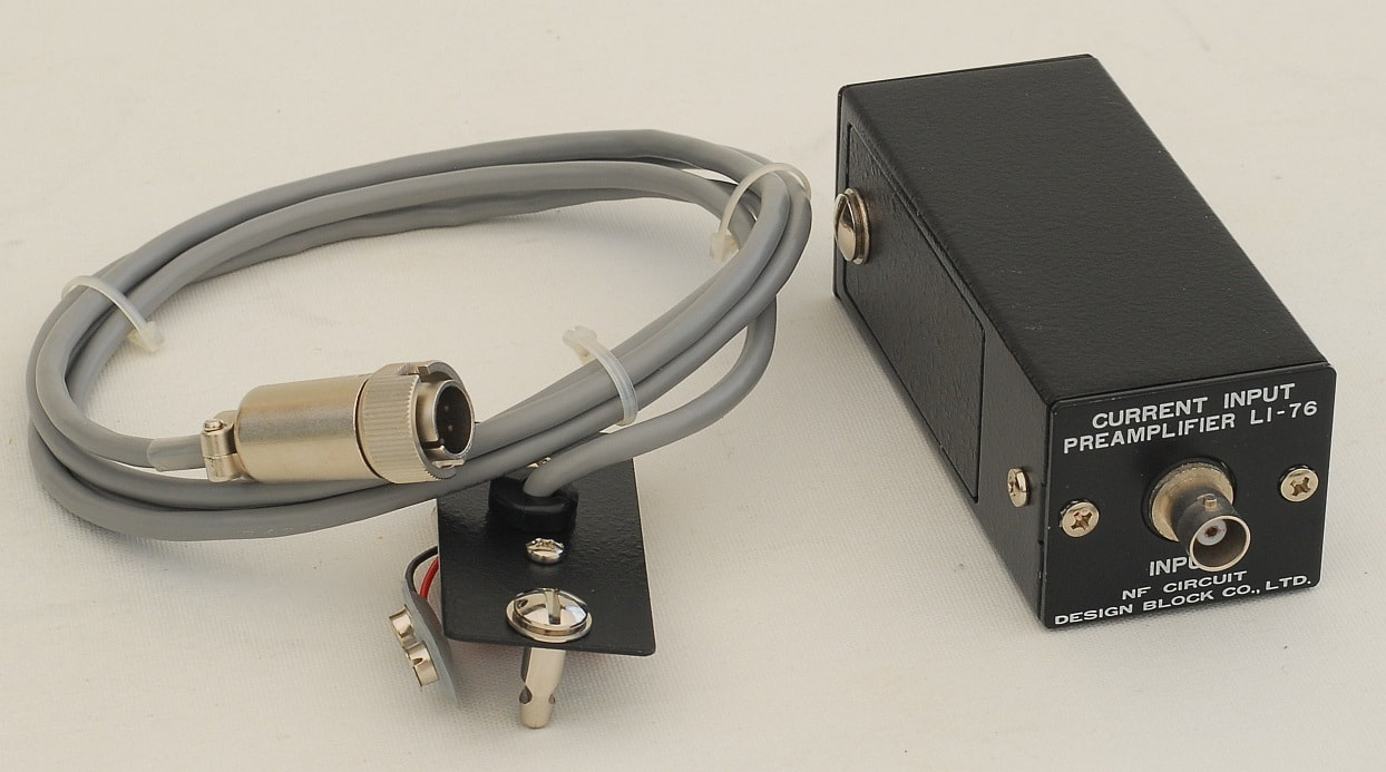
NF Corporation LI-76 Current Input Preamplifier
This is another example of a current amplifier for research, typically used for photo detectors. It is powered by a 9 V battery, or through the power adaptor, also shown here. The 6-pin Hirose power output on NF gear provides ±24 V so the adapter includes two 3.32 kΩ resistors and a 18 V zener diode. The LI-76 is thereby powered by the double voltage when using the power adaptor. The panel receptable is Hirose RM12BRD-6S (RS stock no. 125-8217 or Mouser stock no. 798-RM12BRD-6S(81)) and the cable plug is Hirose RM12BPE-6PH (RS stock no. 537-2186 or Farnell stock no. 1077717). As a side note, the same 6-pin power connector is also seen on some lock-in amplifiers from Ithaco, though the most widespread power connector on Ithaco gear seems to be XLR. |
