ESI 251 Impedance Meter modifications
|
I got my second ESI 251 simply out of curiosity and in order to compare it with the first unit I already had. When it arrived, it was not in working order, but the two issues quickly turned out to be a defective front panel display, and a fried op-amp for the DC output. I should point out that the manual with schematic diagram is available on the Internet and is a great help, indeed.
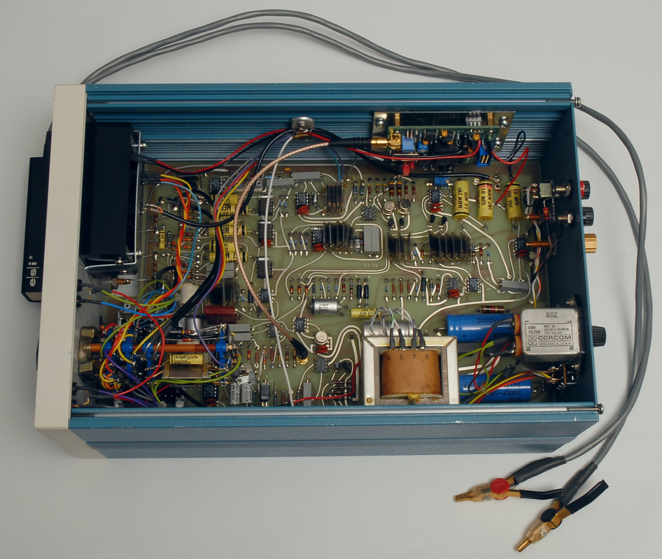
Having replaced the op-amp for the DC output I found that the 251 seemed to work as expected in each range and setting. There are some nice details of the design such as the 0.02 % wire-wound resistors and serviceability, so I decided to spice up this unit. The idea was to address some of the error sources I found by inspecting the diagram: DC errors (offsets and bias), temperature coefficients of the components, in particular those around U13 and U14, limitations of the integrators U16 and U19, and the frequency stability of the generator. In addition to the replacement of the defective Analogic 3½ digit display with a 4½ digit LED display from Murata, including logic to drive the additional decimal point, these were the changes I decided to implement:
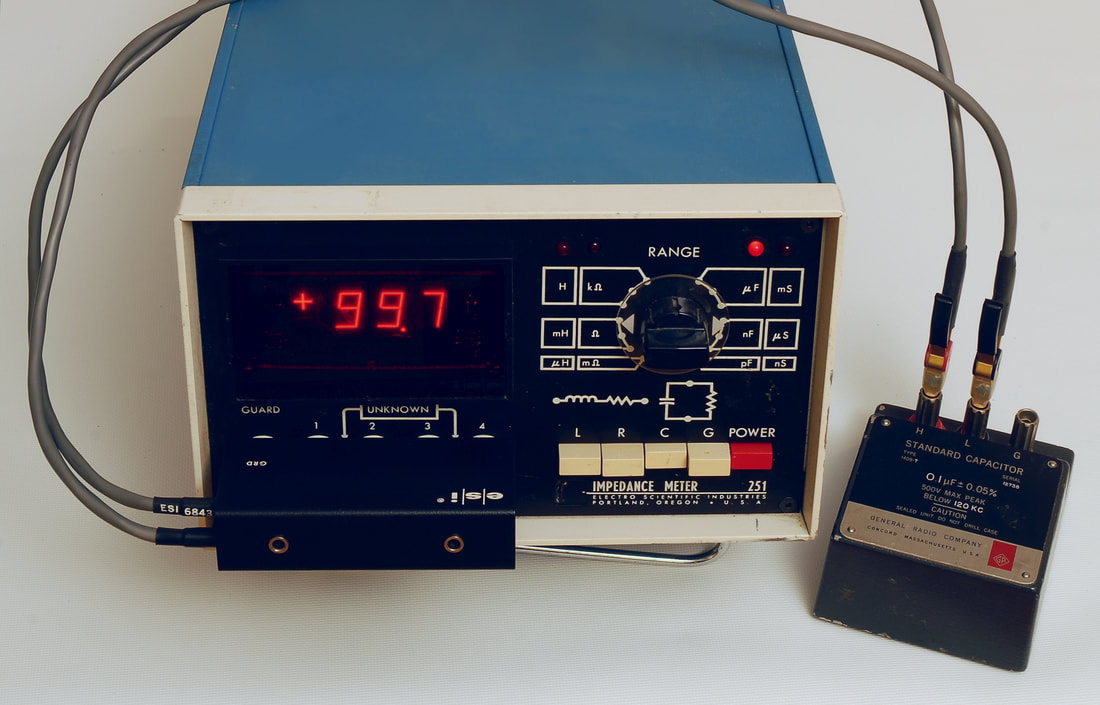
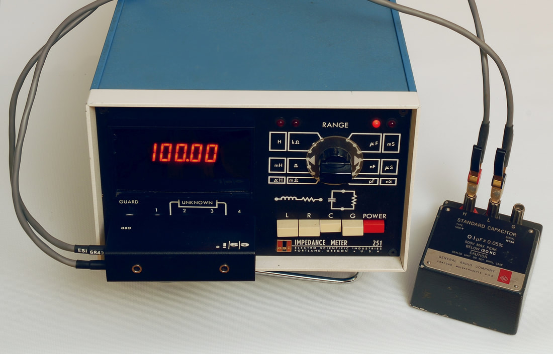
Note: If you want to replace op-amps U19 or U20 (both AD741CN) with another type beware that the trimmer network for offset adjustment may have to be changed. With an OP177GP as U19 and U20 I had to place a potentiometer between pins 1 and 8, rather than pins 1 and 5, with the wiper connected to +15 V, rather than -15 V. The first picture shows the 251 with the new Murata 4½ digit LED module, model DMS-40PC-1-RL-C, available from Farnell (order no. 1339286), and the PLL board to control the 1 kHz oscillator. The two pictures below show the unmodified 251 and the other, modified 251 unit with the new Murata display, while measuring a General Radio 1409-T 0.1 µF standard capacitor. The Murata display requires a 5 V supply, so power is taken from the PLL board. The additional load on the 251's 15 V rail is more than acceptable due to the low power consumption of the LED display and the PLL board. The display compartment is reused to maintain the look of the front panel, but the depth is reduced to improve the cabling and to allow better access to the main circuit board. |
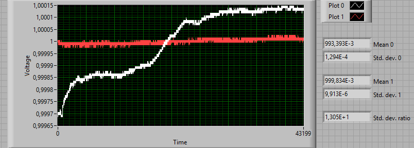
100 nF comparison (General Radio 1409-T 0.1 µF standard capacitor):
White (plot 0) = Original, Red (plot 1) = Modified. 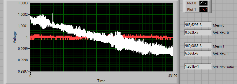
100 pF comparison (General Radio 1408 reference standard capacitor):
White (plot 0) = Original, Red (plot 1) = Modified. |
The upper two graphs show the change of the voltage on the output on the back of the 251, measured with a Fluke 8842A once per second over a span of 12 hours, after 1 hour of warming up, for two different capacitors.
In both cases the standard deviation was reduced with a factor of 13, quite appropriate now that the display includes an additional digit. Further changes, still without altering the design, would include replacing the 1N825 reference with a device with lower temperature coefficient, changing selected trimmers and resistors for better stability, further reduction of the offset errors by introducing offset adjustment on more op-amps and/or by selecting better op-amps, and finally evaluating the stability of the compensation networks and making changes accordingly. |
