Fluke 732A DC Reference Standard
|
The 732A has been an ubiquitous zener reference in DC voltage metrology for decades. To make the most out of the 732A it should get calibrated against a primary Josephson standard, or against a bank of zener references that are calibrated against a primary Josephson standard. Indeed, this is done on a regular basis by national metrology institutes around the globe. Fluke offers an upgraded reference, the 732C, but the 732A is still in widespread use, and well-preserved units with a documented calibration history are highly valued.
The 732A underwent a few changes through the years it was marketed, but the basic design principle remained the same: An ovenized zener/NPN-combination with very low total temperature coefficient, amplified to 10 V. Additional resistive dividers provide 1.018 V and 1 V nominal outputs. |
Above: The battery module with larger holes made for the Yuasa NP4-6 batteries.
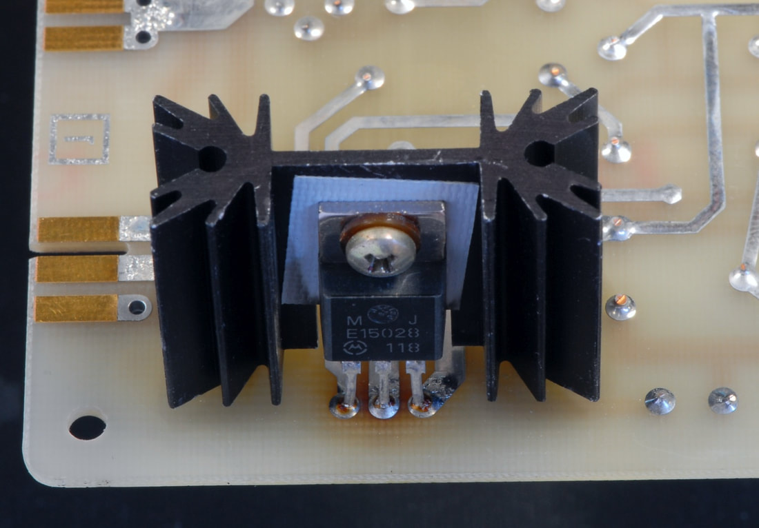
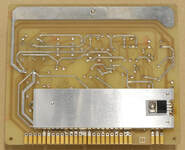
Above: The original heatsink for Q4 on the regulator board, and the new heatsink made from 5 mm aluminium, offering better cooling and mechanical stability. A third screw is added to keep the heatsink in place.
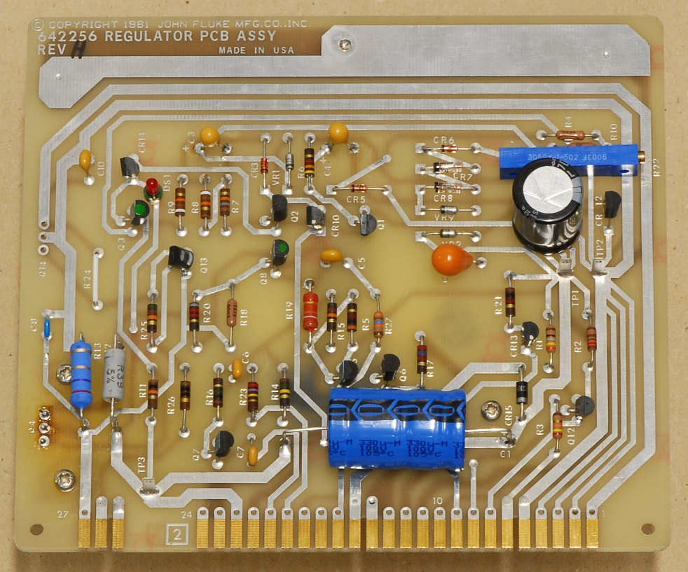
Above: The regulator board with a few components replaced.
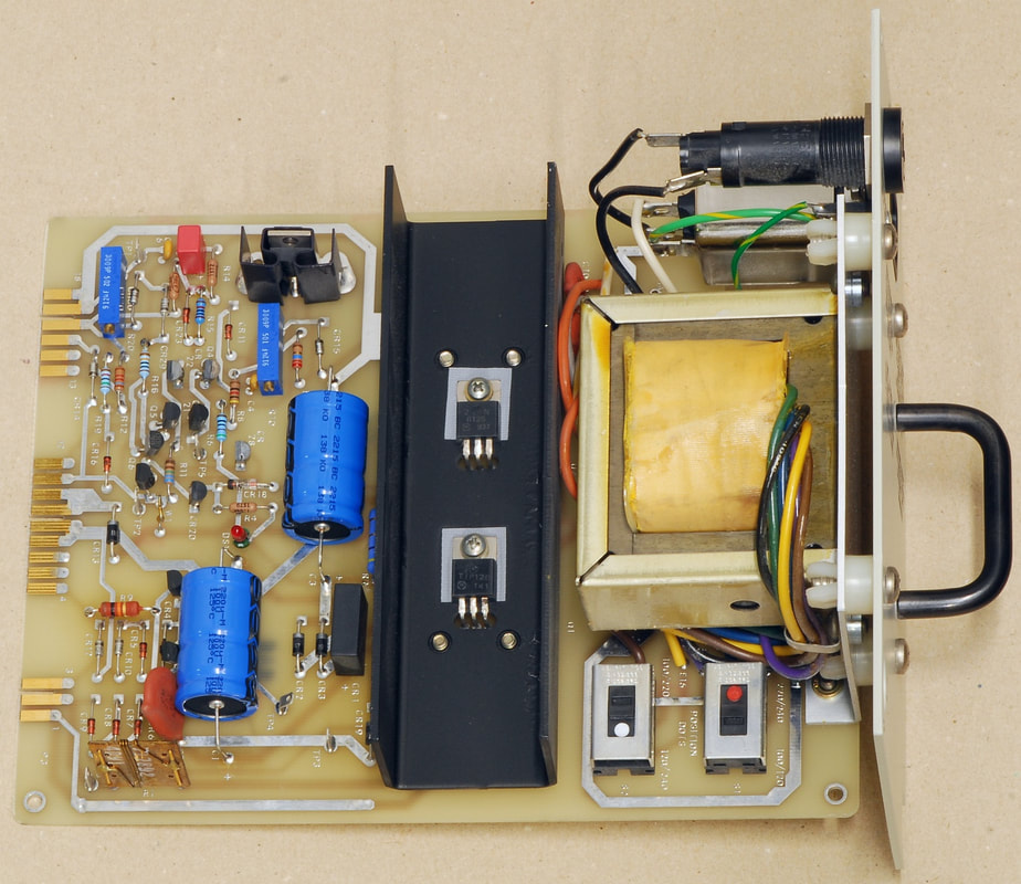
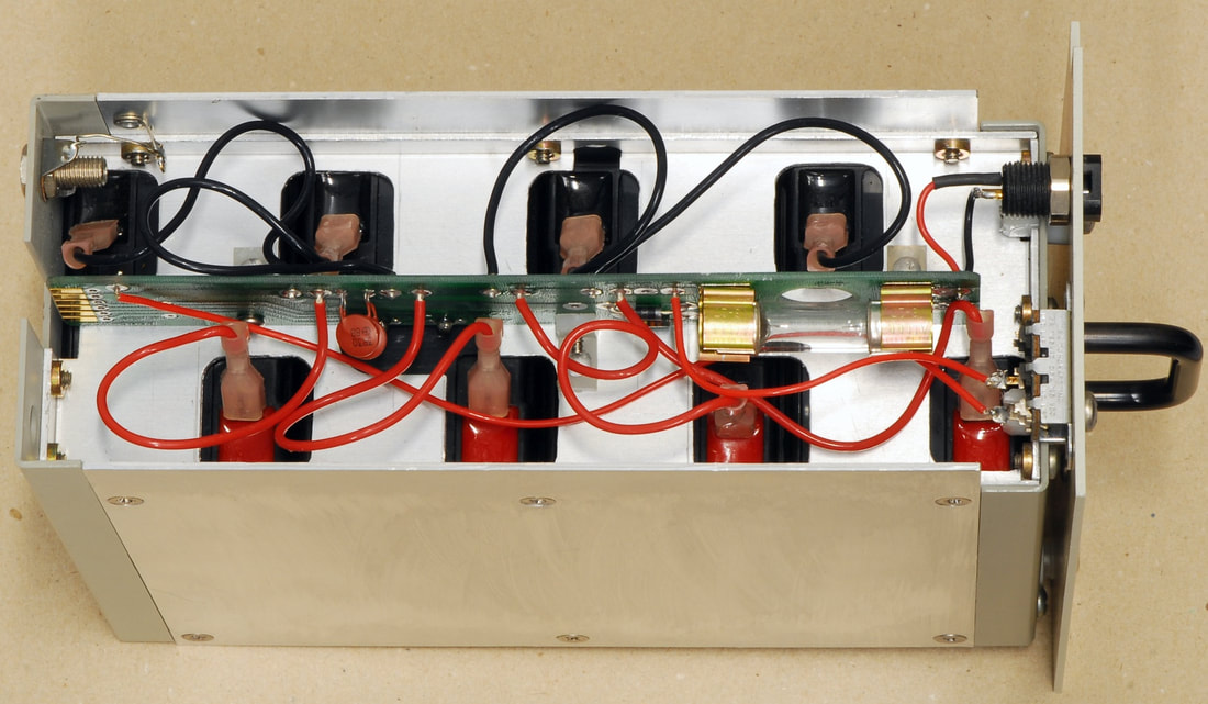
Above: The pre-regulator board with a few components replaced, and with a new IEC power inlet.
|
The 732A needs and deserves to be taken well care of. This includes replacing the batteries at regular intervals before the capacity is reduced so much that it prevents transportation to/from calibration. There are a few hints in the manual as to how one may evaluate the state of the batteries. I monitor the voltage on the power input J10 on the back, as shown further below.
Also, in particular for older units, the electrolytic capacitors may need to be replaced, and any old Schaffner IEC inlet filter should also be replaced, just as a precaution before it erupts a foul smoke. On my unit, which seems to originate from around 1991 or so, based on the date codes identified on components, the A4 Regulator (Rev. H) does not have its power transistor Q4 mounted on the bottom plate as shown in the manual I have (dated May 1986), but on a small heatsink on the A4 circuit board. This definitely helps when taking the 732A apart, but the slight discoloration around the pads for Q4 suggests that the temperature gets too high in this design. I decided to replace the small heatsink with a larger one, mounted in parallel with the board, and supported by a third screw. This also helps to reduce the mechanical stress on Q4 and the pads during transport. The battery module was completely disassembled, and the holes in the top plate were enlarged to allow a set of fresh batteries (Yuasa NP4-6) to be inserted safely. Small rubber feet were added to the bottom plate to keep the batteries in place. I decided to reduce the preregulator's charging current slightly to about 200 mA by increasing R3 from 3.3 Ohm to 4.7 Ohm. This will result in less heat generated, and is close to a the 4 Ah capacity of the Yuasa batteries divided by 20 hours, which I use as a rule-of-thumb when charging lead-acid batteries. Before inserting the assembled battery module in the 732A the batteries were charged independently so that each battery had the same voltage within 50 mV. This should bring the batteries closer to a starting point with comparable charging states. In order to test the pregulator's charging circuitry before letting it charge the new batteries, I made a load based on a PNP power transistor to mimic a battery with adjustable voltage. While "charging" the electronic load, the voltage across the load was set to 26.5 V. Then, R10 was slowly turned down until DS1 turned off, and R20 was adjusted to a trickle charge voltage of 25 V. During the test 10 kOhm resistors vere mounted in parallel with R11 and R12 to simulate that the thermistors in the battery compartment were connected to the preregulator. After the overhaul, the 732A is now under power - again - and it will be left on! The plan is to check the stability during the coming months, and then to have it calibrated by the start of 2023. |
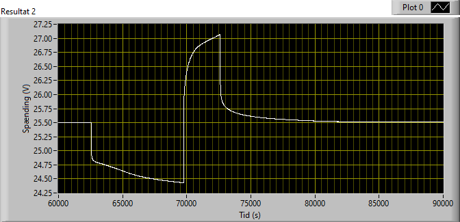
Graph above: The voltage on J10 of the 732A, depicting a sequence of discharge when disconnecting the mains, and charge when the mains is connected again, recorded at an ambient temperature of 23 C. The discharge slope can be used to estimate the battery condition. Note that the expected time the 732A can be left without mains power drops at lower ambient temperatures.
|
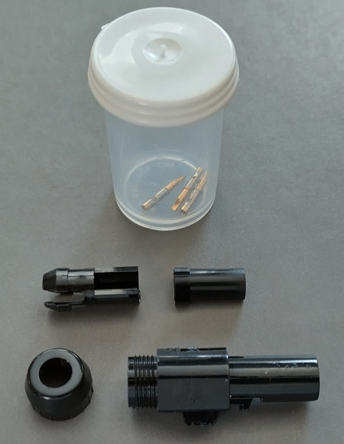
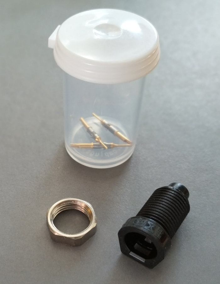
It's not easy to find the proper plug for the J10 power input, but one is available from TTI: Hypertac D01PB306FSTAH.
If you need the corresponding connector for the chassis, this is the one: Hypertac D01EEB306MST, also available from TTI. I have made a cable terminated with the Hypertac plug D01PB306FSTAH at one end and banana plugs at the other end. This allows me to monitor the battery voltage, and to charge the batteries, through the J10 connector. Note that a multimeter with eg. 10 MOhm input impedance will load the 51 kOhm resistor which shunts the input diode of J10 so that a correction of the measured voltage is required. By monitoring the voltage on J10 when removing the mains power from the 732A you can evaluate the condition of the batteries. The graph on the left shows the measured voltage (corrected for the voltage drop caused by the 51 kOhm output resistor) over a period of 2 hours without mains power. The graph also demonstrates that I have set the fixed voltage by the charger circuitry to 25.5 V, and the trip voltage for the initial constant current charging to slightly above 27 V. For transporting the 732A for a longer period of time by car I use a DC-DC converter box which converts the car battery power from a cigarette lighter outlet to 25.5 V. This voltage was chosen so that the converter within an hour or so will supply practically all of the power to the 732A through J10. Some use a battery to mains inverter to power the mains input of the 732A, but I'm not not a huge fan of this solution as many inverters output AC voltages that have far from sine shape. |