Halcyon OFS-1 Modification
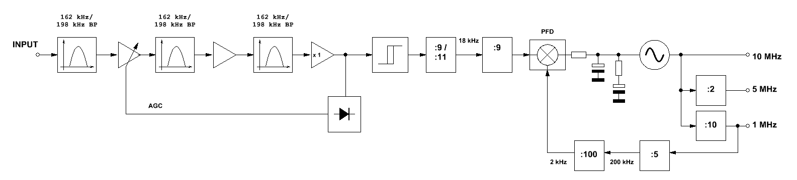
Above: Simplified block diagram of the original Halcyon OFS-1. The ferrite antenna and pre-amplifier are not shown. Note how the analog signal passes a Schmitt-trigger and enters a divider. This is a fatal design flaw.
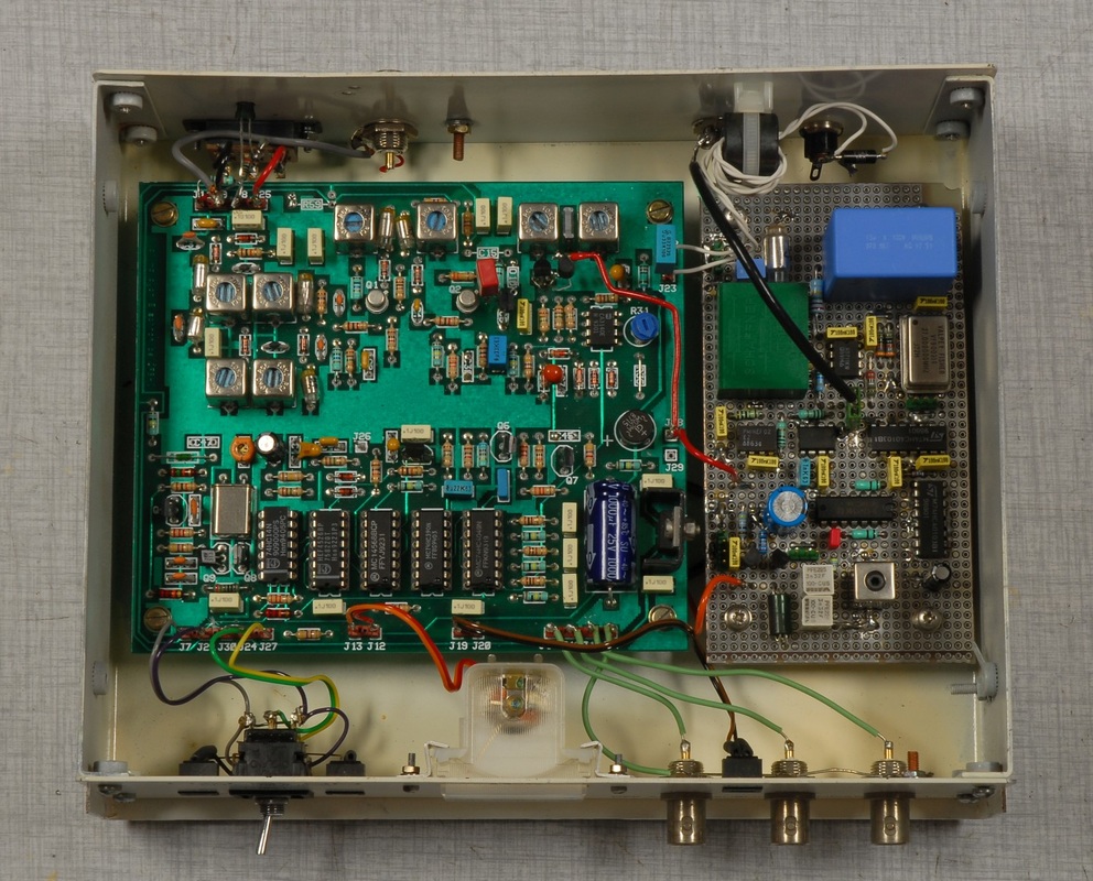
The modified OFS-1 with the auxiliary PLL on the right. The large, blue 15 uF film capacitor in the upper right corner of the board is used for the integrator of the PLL control amplifier.
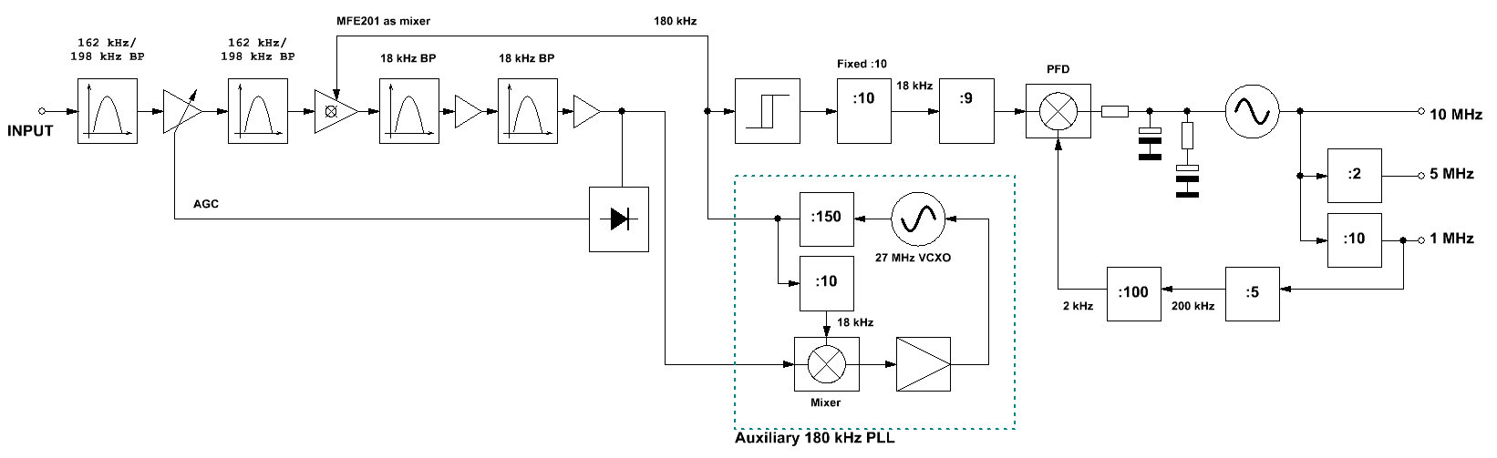
The block diagram of the modified OFS-1 with the auxiliary PLL in the blue dotted box. The original PLL takes no part in the reception of the signal but merely extracts 1, 5 and 10 MHz from the 180 kHz signal provided by the auxiliary PLL.
|
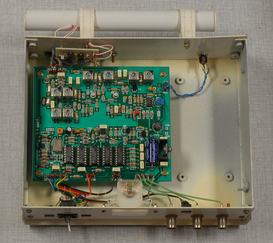
The upper picture shows the inside of the OFS-1 in its original, unmodified condition, with the exception of the frequency selector that had been replaced by the previous owner.
The issue with the OFS-1 is that it's very sensitive to any glitch that appears during the reception. It has a hard time obtaining lock, and this will only last until fading or noise appears. The OFS-1 was clearly designed to be used very close to either the BBC 4 or the France Inter transmitter. I have reverse-engineered a schematic diagram and a block diagram as I have not been able to retrieve any documentation on the OFS-1. One major design flaw is that the OFS-1 applies a frequency divider directly to the amplified and filtered 162 / 198 kHz signal. This makes the design vulnerable to interference, fadings and all sorts of noise. The input signal, being analog, should be treated as such, and not like a digital signal. Any glitch will cause a missing or an additional count, so the design is inherently prone to cycle slips. Any attempt to add further input filtering remains a fix and is no real solution. The OFS-1 uses simple, switchable LC filters for selectivity, whereas the sister model, the OFS-1A, is said to include quartz filters in order to reduce interference. It's clear why Halcyon would have found it necessary to make this change, but it's no remedy at all. The OFS-1 called for a major rework, and I considered two approaches: A) Downmixing the 162 / 198 kHz carrier to 2 kHz with a selectable 160 / 200 kHz clock derived from a new 40 MHz VCXO, and use a multiplying phase detector running at 2 kHz. The wanted 1, 5 and 10 MHz may be derived directly from the divider chain. Though the second dual gate MOSFET could be used for downmixing substantial changes would be required and the original digital circuitry would be rendered useless. This effort is hardly worthwhile so I devised an alternative approach: B) Downmixing to 18 kHz with a fixed 180 kHz clock, and use a multiplying phase detector running at 18 kHz. It turns out that it's rather straightforward to modify the existing design for this: The solution is to make a simple auxiliary PLL which accepts the 18 kHz signal and outputs a 180 kHz clock for the downmixing and for the existing divider chain to extract the 1, 5 and 10 MHz signals, provided the selectable :9/:11 divider is modified to a fixed :10 ratio. Having realized during a series of test runs how absurdly sensitive the OFS-1 design really is to common reception anomalies, I decided to build the auxiliary PLL. The block diagram shows where to interface to the existing design. The auxiliary PLL is based on a standard 27 MHz VCXO and a balanced switching mixer. The second dual gate MOSFET of the OFS-1 is now used for downmixing, and the switchable 162 / 198 kHz output bandpass filter now serves as a double 18 kHz filter with additional gain in between to compensate for the conversion loss. The rectifier for the AGC was slightly modified to keep about the same AGC voltage over the input range as the original design. The memory effects of the sequential logic (counter and phase-frequency detector) are now gone. You may even remove the antenna signal, leave it off for a couple of minutes, and the PLL will immediately re-enter lock when you apply the signal again, thanks to the low drift of the loop amplifier. Another advantage is that there's less amplification at the 162 / 198 kHz reception frequencies, resulting in a reduced risk of pick-up should one use the unit's ferrite antenna. For reasons of flexibility and signal quality I removed the antenna and use an external loop or E-field antenna. The switch to select between the internal and external antenna now serves the purpose to switch on/off power for the antenna. The downside of the auxiliary PLL is that the acquisition may take a while, but it's still within an acceptable limit, at least for my purposes. An acquisition help circuitry would admittedly be of value, but for now, I enjoy having rescued the OFS-1 from recycling and being able to put it into use for experiments. Should you decide to add an acquisition help circuit note that you may indeed include sequential logic as long as you do not apply it in the fashion of the original OFS-1 design. |
