Repairing the Hewlett Packard 4282A
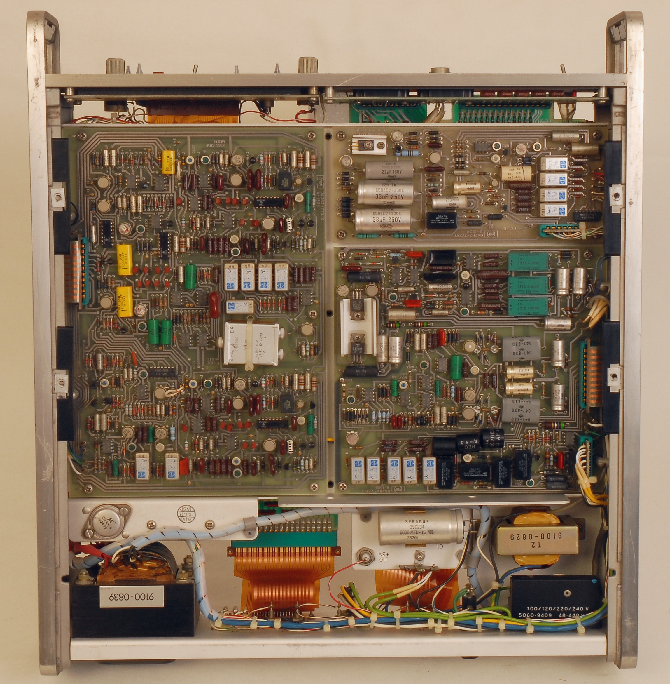
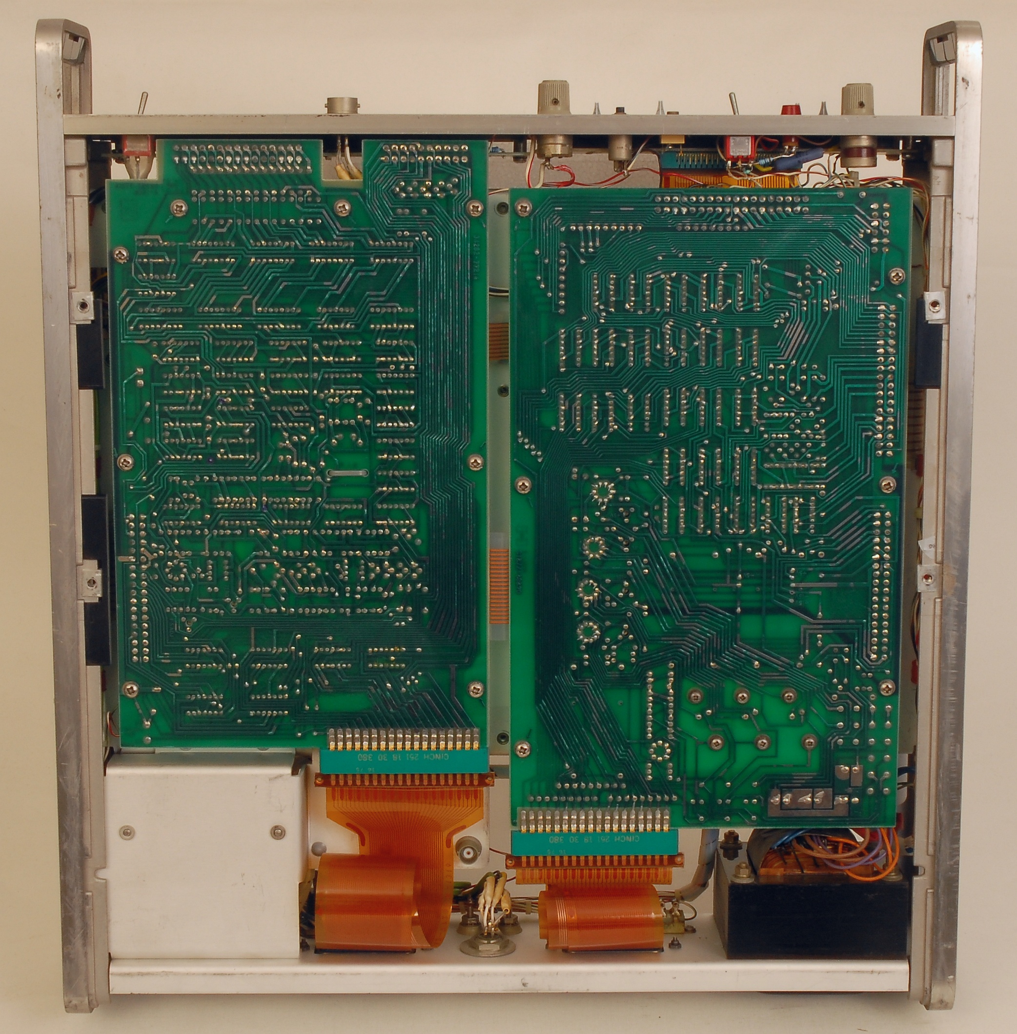
Top row: Top and botton views on the 4282A.
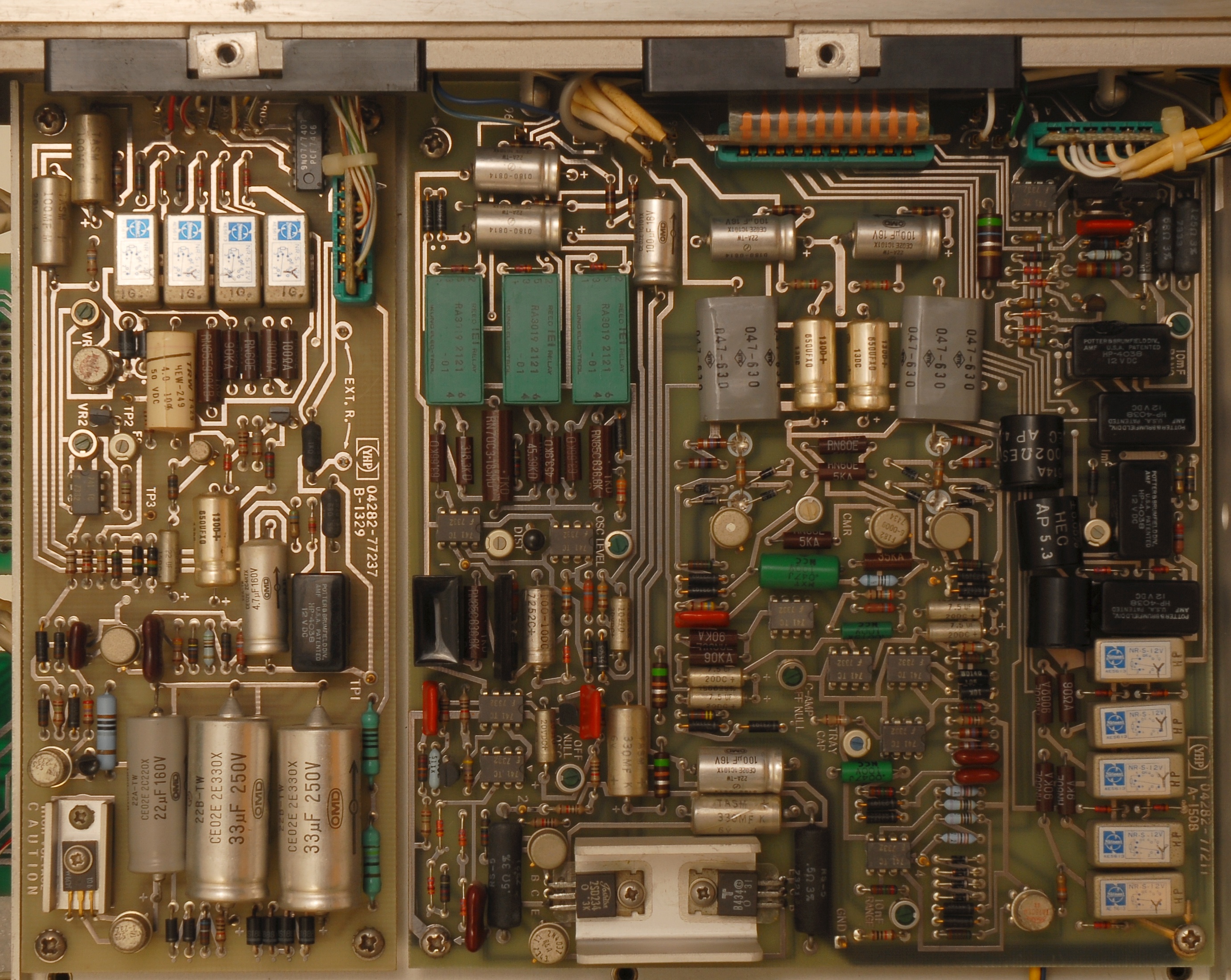
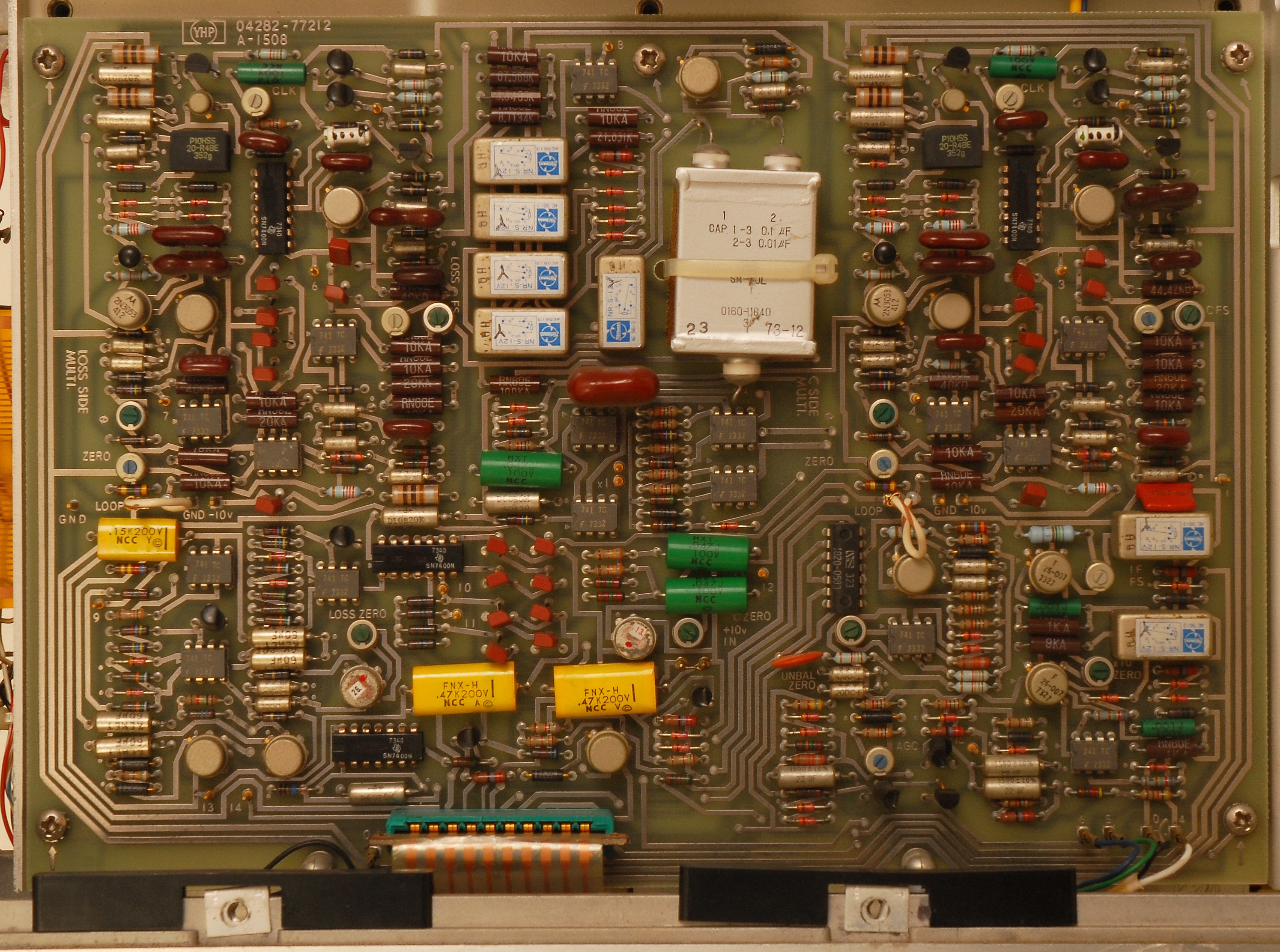
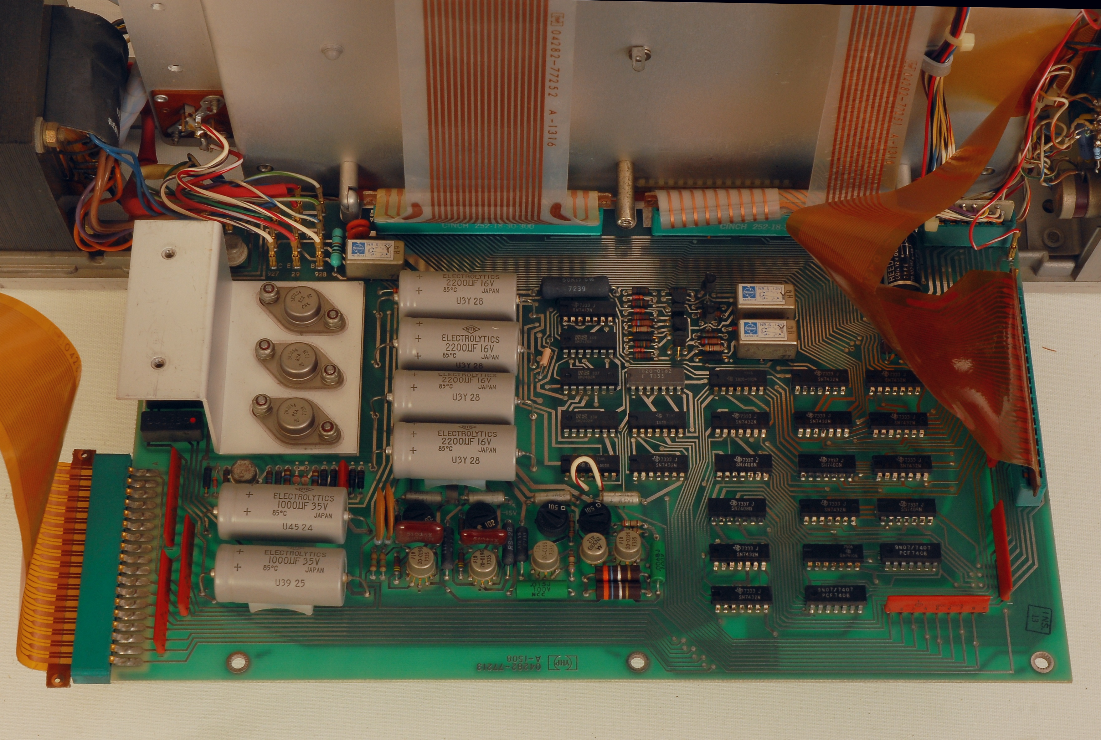
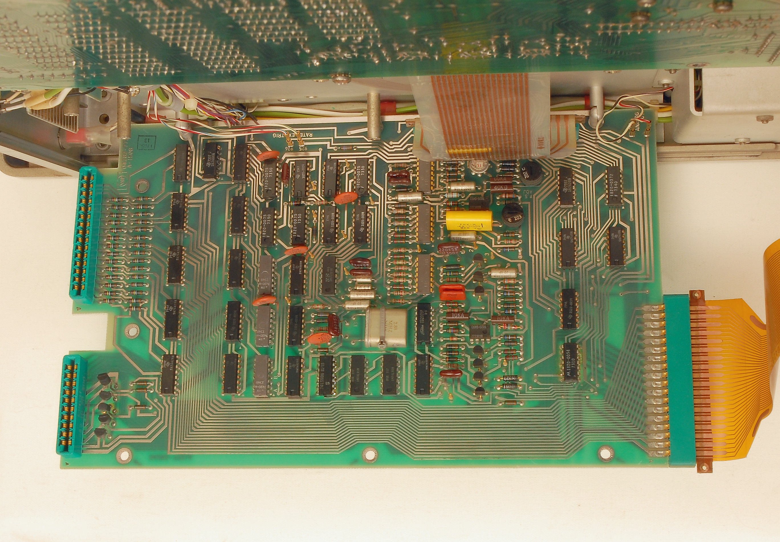
Row 2: Close-up of the oscillator and leakage boards (left), and of the multiplier board (right). Row 3: Close-up of control/power board (left), and of the DVM board (right). |
The 4282A is an interesting design, but be prepared to spend time on debugging and repairing. The mechanical design with the hinged boards helps, though you cannot keep the display board A5 and the DVM board A4 connected is you want to access the upper side of the DVM board. The service manual, as always, is a must for anyone wanting to take a closer look inside, but the version available from Keysight on the Internet is of poor quality. The pictures I have uploaded should be a help (click on the pictures to get a higher resolution).
The unit I got from Ebay had a number issues that had to be fixed: There was no reading, but all zeroes; Turned out to be a faulty 74LS90 counter in the PWM divider chain on the DVM board A4. Missing indicators lights; I replaced all incandescent bulbs with red LEDs, and changed resistors R6, R7, R8 and R10 on the display board A5. For the three indicators to the right (UNBAL, OVERLOAD and CHECK FUSE) two LEDs in series, with 100 Ohm as the current limiting resistor, work fine. With the indicators being red and not dark orange, the result is also more appealing visually. No 10 V bias; The output transistors Q9/Q10 and the protection zener CR12 on the oscillator board A1 had to be replaced. Indeed, a strong evidence that a discharge event took place in the past, either due to a charged capacitor applied to the 4282A, or due to fiddling with the settings when using the 100 V bias function (read also the description of the 4282A on the impedance pages). The UNBAL indicator was continuously lit due to a defective transistor Q15 on DVM board A4. The readings in the 1 F range remain to appear unrealiable; I suspect the contacts for the relays for the range resistors to have suffered burn-out during discharges, but this needs to be investigated. There was excessive relay activity when operating the sliding switches on the front panel. By cleaning the contact surfaces this improved, but the design remains weak, and one should expect unwanted relay activity when operating the 4282A. The bias toggle switch, when operated slowly, could result in a state where the bias ON indicator light was off, but the bias circuitry was actually still active! A result of having a separate pole for the lamp in combination with a bad contact for the pole actually activating the bias circuitry. The bias switching arrangement was redone to avoid erroneous states. An important lesson learned from the repair session is that the 100 V bias feature is a flawed design, bound to lead to failures. For that reason, I will not use the 100 V bias feature, ever. I suspect that models without option 001 are less prone to failures, so if your are looking for a 4282A I would not pay extra to get option 001. What now remains is a thorough adjustment and calibration session ... more to follow ... |