Impedance standards
|
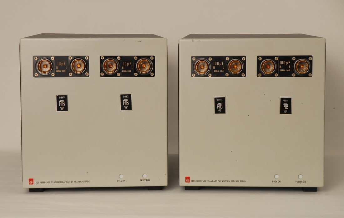
General Radio / GenRad / IET 1408 Reference Standard Capacitor
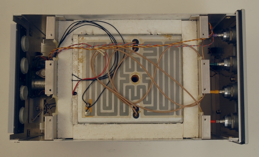
The 1408 features a set of highly stable fused silica capacitors engineered for metrology applications. With a temperature coefficient about 12ppm/C, the capacitors are mounted in a regulated temperature chamber to allow calibration down to the 0.1 ppm range. The standard 1408 offered by IET is a 10 pF / 100 pF combination. The two units shown here have 2 times 10 pF and 2 times 100 pF. This likely explains the sticker "Special Modification 1408-9001" on the back of the 2 x 100 pF unit. The connectors are gold-plated GR-874 types, and will require an adaptor to put the 1408 into use. Two GR-874 to BNC adaptors plus two BNC T-adaptors will allow connection of the 2-terminal 1408 to standard 4-terminal interfaces on LCR-meters. The units should ideally be left permanently on. For the same reason, I have replaced the small light bulbs type "382" for the power and oven indicators with LED lamps having the same socket. I use 24 V types, Farnell 769-3028, which give a very bright light when powered from 12 V. Note that the wires to the lamp sockets have to be swapped in order to ensure correct polarity for LED lamps with positive center (I recommend that you check the wiring and polarity before making any changes). The lower picture shows the inside with the upper layer of insulation removed. An adhesive heater foil heats up the compartment where the capacitors are located. The thermostat is located in the slot to the left, connected with two red wires. The coax cables, which appear to be RG-316, endure a small bending radius close to the output connectors, and one wonders why the designers did not punch slots that align with the four connectors to allow stress-free passage of the cables. |
|
(Picture to be added)
|
General Radio / GenRad / IET 1406 Coaxial Capacitance Standard
These are one-terminal pair or one-port (1P) type air capacitors to be used as working calibration standards for impedance analyzers featuring a coaxial connection, or for LCR meters with common 4-terminal BNC interface in combination with an appropriate test fixture or adapter. The connector is a GR-900 type, directly pluggable into the Hewlett Packard 16021A test fixture, or into a Genrad type 1615-P2 adaptor for the Genrad 1615-A capacitance bridge for calibration. To see how to use a 1P impedance with 4 -terminal instruments consult Bryan P. Kibble: "Four terminal-pair to anything else!". The Hewlett Packard 16021A fixture corresponds to the Figure 7 in this reference, though the H and L pairs are swapped. For further reading on terminal definitions consult L. Callegaro: "Electrical Impedance Principles, Measurement, and Applications". I have a 50 pF 1406-E and a 1000 pF 1406-A, both used to maintain the Hewlett Packard 4271A 1 MHz Digital LCR Meter. Among the capacitors specified in the 4271A service manual are a 1406-D 100 pF and a 1406-D 1000 pF. However, for the 100 pF range the 50 pF 1406-E works just fine. |
|
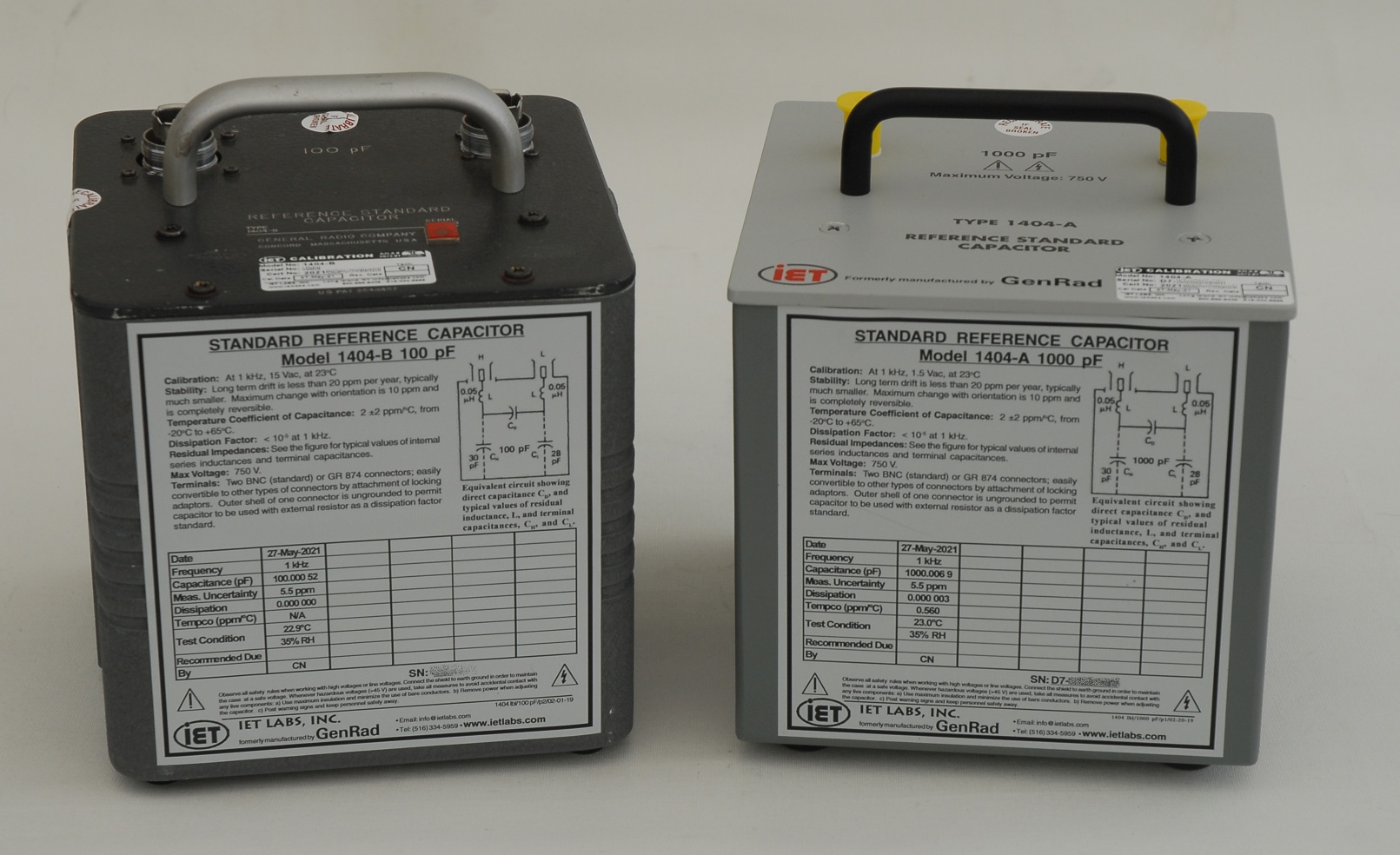
General Radio / GenRad / IET 1404 Standard Reference Capacitors
The capacitors of the 1404 series are intended as reference standards of capacitance, used for comparisons with working standards or for general impedance metrology. The 1404 offers great stability (specified to better than 20 ppm per year), only surpassed by fused silica capacitors. The 1404 should be used in the same orientation as during its calibration as there's a slight, though reversible, change of capacitance with orientation, specified to be less than 10 ppm. The picture shows a new 1404-A 1 nF capacitor (with BNC connectors) from IET Labs, and an older 1404-B 100 pF capacitor (with GR-874 connectors) from General Radio. In terms of metrology, the 1404 capacitors are considered two terminal-pair or two-port (2P) impedances. |
|
(Picture to be added)
|
General Radio / GenRad / IET 1409 Standard Capacitors
These are silvered mica capacitors, for capacitances up to 1 µF, to be used as two or three-terminal working standards. They may be used for common 4-terminal BNC interfaces in combination with an appropriate adapter, such as the Andeen-Hagerling AH TTA1 or similar. Values from 1 nF to 1000 µF in decade steps are available from IET Labs. The values from 10 µF and above come in larger casings, and are metallized polypropylene sulfide (MPPS) capacitors, with a maximum working frequency of 1 kHz and a rather low maximum working voltage of 22 V RMS, compared to the mica types. Older Genrad models can be found with values in an 1-2-5 sequence, up to 1 µF. My lab features a set of a 1 nF type 1409-F, a 10 nF type 1409-L, a 0.1 µF type 1409-T, a 0.5 µF type 1409-X, and a 1.0 µF type 1409-Y. The banana plugs seem to be missing on many used units, but may be replaced with Digikey 501-1589-ND. |
|
(Picture to be added)
|
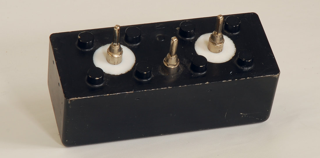
Adaptor for 2-terminal components
Connecting the 1409-series capacitors to a common 4-terminal LCR meter is not trivial and should be done correctly, and in the same fashion each time. I decided to make a adaptor that accepts the 1409-series to avoid all the hassle, and to facilitate measurements in a temperature chamber, for instance. The switch allows measurements with the 1409 coupled in either 2- or 3-terminal mode. I trust a reliable APEM series 12000 toggle switch with solid gold rivets for this job. |
|
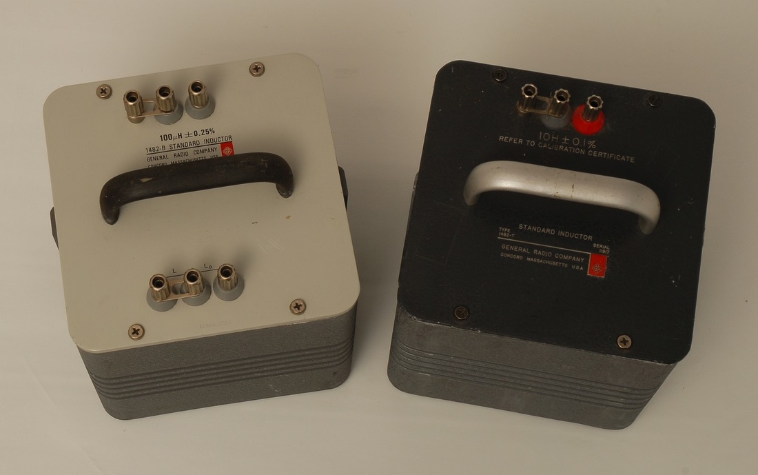
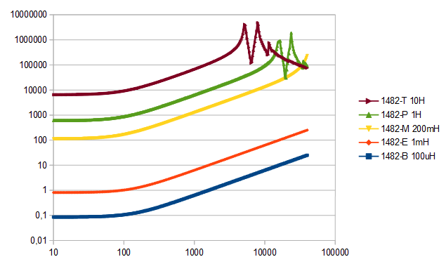
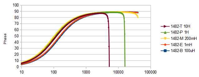
General Radio / GenRad / IET 1482 series inductors
If you're seriously into AC impedance you'll need a set of calibration inductors to supplement your set of calibration capacitors. Originally designed by General Radio decades ago but now manufactured by the IET Labs, Inc., the 1482 series is omnipresent in the world of low-frequency laboratory inductance standards. The two values shown in the picture, 100 μH and 10 H, are the highest and the lowest value in my humble collection. You should consult the documentation from IET and the literature before putting these inductors into use. If not applied correctly, the series resistance or the resonant frequency are likely to play a trick. The lowest values in the 1482 series have 3 additional terminals that allow you to connect the test terminals to a short or to the inductance. This makes it possible to subtract the lead inductance from the measurement. The graphs show the impedance and the phase for 5 inductors from the 1482 series over the frequency range of 10 Hz to 40 kHz, measured with the impedance adapter and the NI USB-4431 as shown above. Note how the knee of the impedance curves as well as the phase curves coincide to put the 1482 Series into use as a Q reference around 100 Hz. From these measurements we get: 1482-T : L = 9,99770 H @ 100 Hz, Q = 0,972 @ 100 Hz 1482-P : L = 0,999700 H @ 100 Hz, Q = 1,040 @ 100 Hz 1482-M : L = 199,974 mH @ 100 Hz, Q = 1,124 @ 100 Hz 1482-E : L = 0,999427 mH @ 1 kHz, Q = 0,775 @ 100 Hz 1482-B : L = 99,943 μH @ 10 kHz Q = 0,733 @ 100 Hz |
|
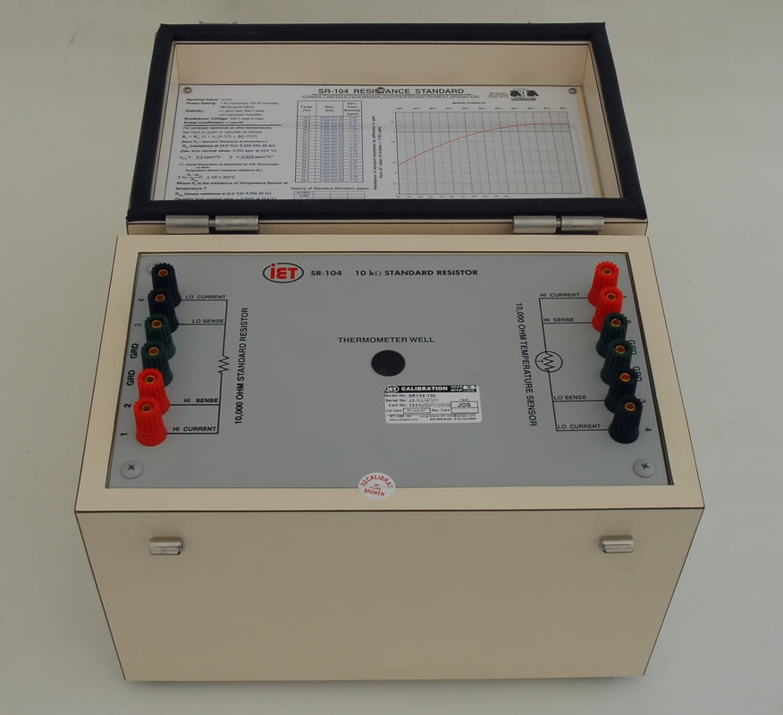
ESI / Tegam / IET SR-104 Standard Resistor
These resistors are widely acclaimed for their stability, and are used in calibration laboratories for providing traceability to working standards, and for general impedance metrology. In view of the stability, the resistors deserve to be calibrated as close as possible against a primary calibration system based on the quantum Hall effect. In the same family you find the SR-102 (100 Ω), and the SR-103 (1 kΩ), though the SR-104 seems to be the model which is found most commonly. The SR-104 has a long history and is found with both ESI, Tegam and IET Labs labels. IET Labs acquired the resistance products from Tegam in 2007, while Tegam acquired the resistance products from ESI, (Electro-Scientific Industries) in 1993. Since the introduction in the late 60's the SR-104 has undergone a few changes. Most obvious is the artwork of the plate inside the casing and the change of binding posts, but more important is the change of the actual resistors: In the time of ESI, the resistors inside the SR-104 were made of Evanohm-R wire wound on a mica card. Today, the SR-104 uses custom hermetically sealed oil-filled Bulk Metal® Foil resistors. The particular specimen of the SR-104 shown here has a fairly high temperature coefficient around 23 °C, with an alfa value of 0.2 ppm/K, as it's not an ordinary production unit. However, it still features a full calibration with values documented from 18 to 28 °C, and shows a zero temperature coefficient around 27 °C. Equally important, the resistors used in this unit have aged more than 15 years so that the stability is expected to be better than ±0.5 ppm/year. |
|
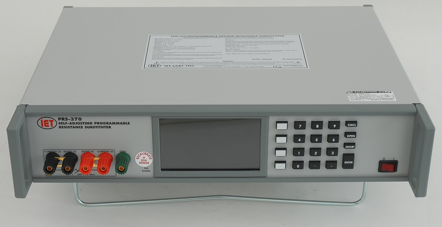
IET PRS-370 Self-Adjusting Programmable Resistance Substituter
The PRS-370 is the modern version of your decade resistance boxes, and provides much better flexibility as resistance calibrators such as the old Fluke 5450A Resistance Calibrator. Inside the PRS-370 there are 43 resistors which are combined in series and/or parallel to get the required resistance. This gives the PRS-370 a specified accuracy of ±(70 ppm + 1 mΩ), and a stability of ±50 ppm/year, over its range of 0.1 Ω - 20 MΩ. The resolution of the PRS-370 is 1 μΩ or 6 digits. As a clever feature, you may connect a DMM (Fluke 8508A, 8588A or the Keysight 3458A) to the PRS-370 via the IEEE-488 interface, and the PRS-370 may then go through a calibration procedure by which the DMM measures the resistance, and the PRS-370 adjusts the resistance in order to minimize the uncertainty. In this way, your DMM acts as a transfer standard and provides traceability to the PRS-370. After this calibration, IET claims that the short-term accuracy without switching is improved to better than 10 ppm, and that the typical accuracy over 24 hours becomes ±(30 ppm + 300 μΩ) for values <1 MΩ, and ±60 ppm for values > 1 MΩ. Finally, there's a complete calibration history stored in memory, listing the value of each of the 43 resistors over time. This is of much value to a calibration lab, and helps protecting the investment in a PRS-370. |
|
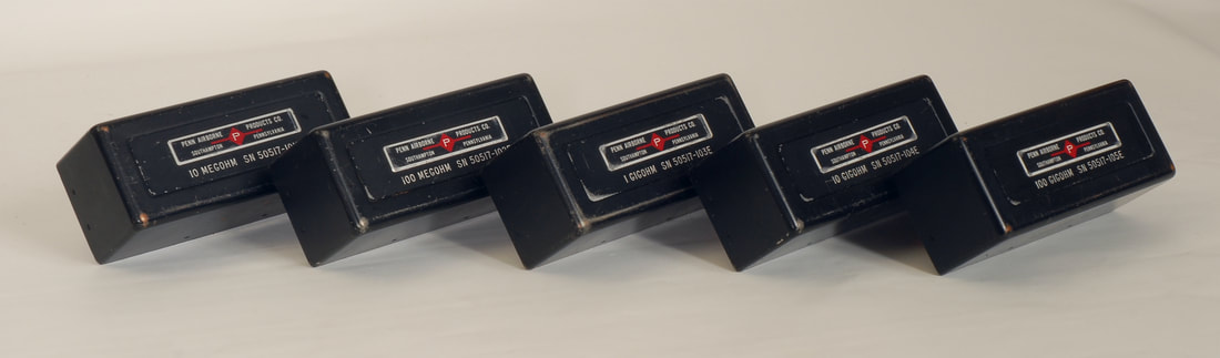
Penn Airborne high-value resistors
For servicing and calibrating low-current, high-impedance gear, what you need is really a proper set of high-value reference resistors. The resistors shown here are the rarely found Penn Airborne resistors, ranging from 10 MOhm to 100 GOhm. To put these beauties into use you will need an adaptor, such as the Guildline model 65201, designed specifically to allow the Penn Airborne resistors to be connected to the Guildline 6530 TeraOhm-Bridge Meter Series or the 6520 Teraohmmeter. Alternatively, you will need to make your own adaptor, paying close attention to screening and leakage. Other, newer models of high-value resistors are available, such as the 6636 series from Guildline, the 100-series from Ohm-Labs, the SRC series from IET Labs, or the 9331G series from Measurements International. You may also try to build your own high-value resistor from readily available resistors, but the temperature coefficients may call for a temperature regulated enclosure. |
|
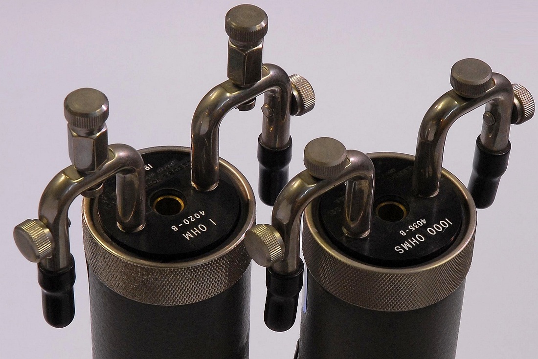
Leeds & Northrup 40xxB resistors
The lab features a few calibration resistors of the Leeds & Northrup 40xxB series to calibrate instruments, and to carry out ratiometric measurements of resistance. In addition to the two Leeds & Northrup type 4020B 1 Ohm and type 4035-B 1 kOhm in the picture, you will find a Leeds & Northrup type 4025B 10 Ohm, type 4030B 100 Ohm, and type 4040B 10000 Ohm in the collection. |
|
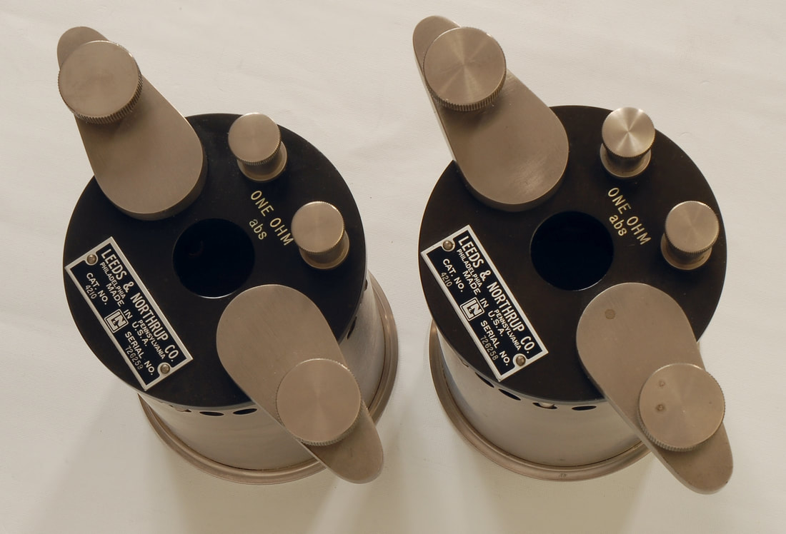
Leeds & Northrup 4210 resistor
The L&N model 4210 Thomas-type one-Ohm standard resistor has served as a working standard for decades. The 4210 resistor is a commercial realization of the resistor described by James L. Thomas based on his investigations of resistor stability dating back to the 1920's. The two resistors shown here originate from a calibration lab that decided to abandon resistance calibration services. |
|
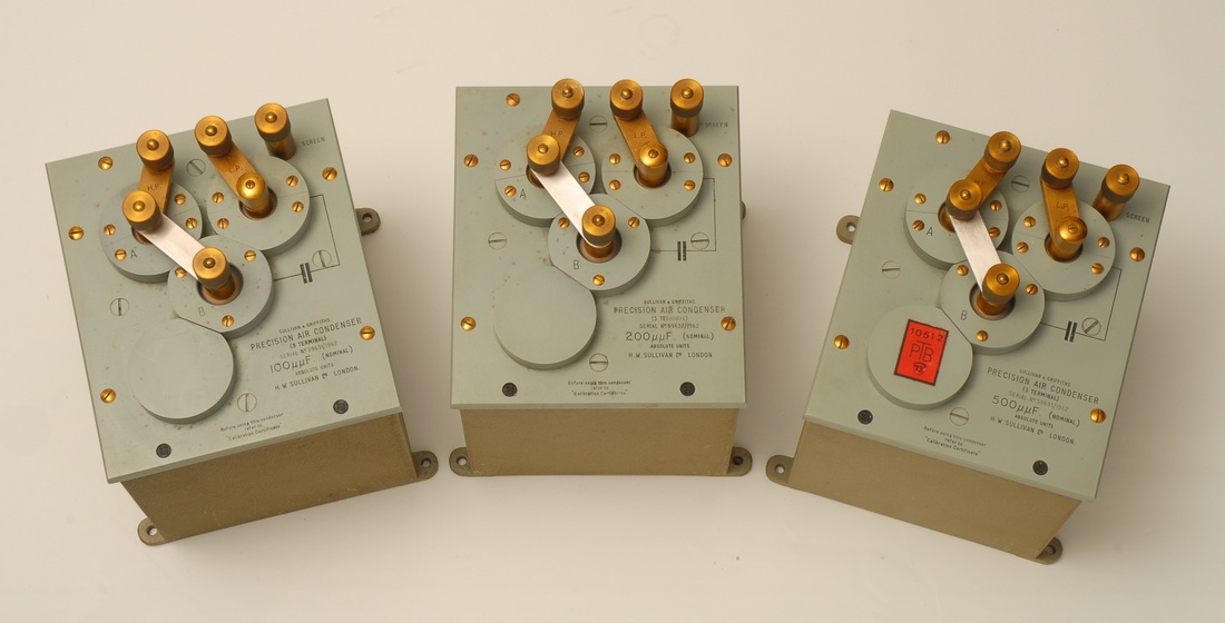
H. W. Sullivan Ltd., Precision Air Condenser
These nicely crafted items of electromechanical engineering are 3-terminal reference capacitors, type "Sullivan & Griffiths Air Condenser". The 3 units shown in the picture have 100 pF, 200 pF and 500 pF capacitance. The serial numbers suggest that the capacitors were manufactured in 1962, and the last calibration was in 1973. I have not been able to dig up any solid information on these, so if you happen to know something about this familiy of capacitors, I would be grateful if you could get in contact with me through the contact form. |
|
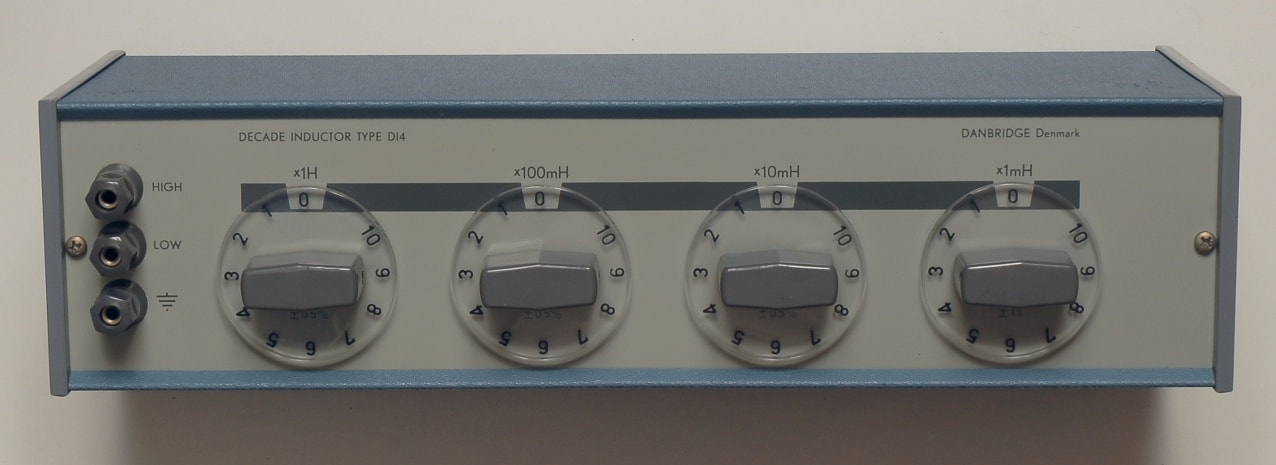
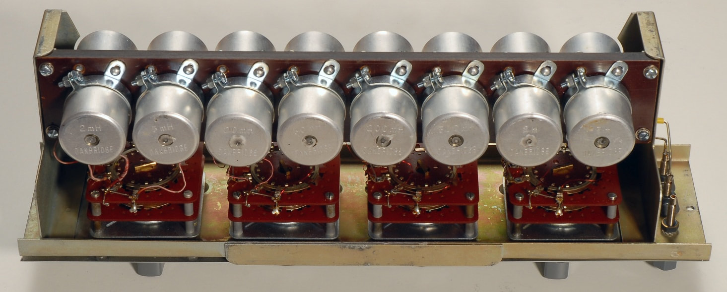
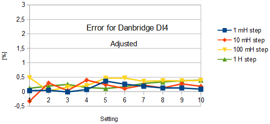
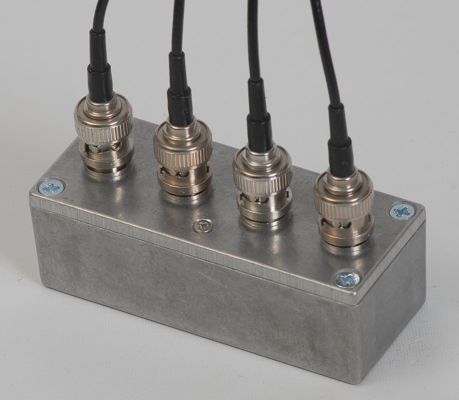
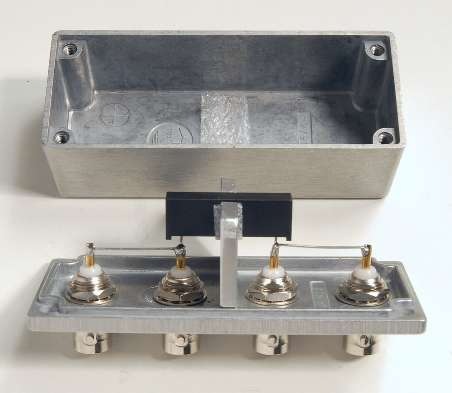
Danbridge DI4 Decade Inductor
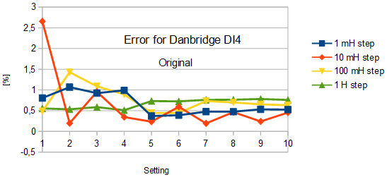
A decade inductor is a useful addition to the more commonly found decade resistors and decade capacitors, and comes handy for servicing of impedance measuring instruments, for filter experiments, etc. Commercially available decade inductors are not precision instruments, and the DI4 is no exception with its specified accuracy of 0.5 % to 1%. It is, however, difficult to find decade inductors that come with a much better accuracy than this. Also, the specified accuracy is not the only parameter to consider. The frequency dependency, the maximum allowable DC current, the temperature coefficient, and the stability over time are of equal importance. The picture shows how the DI4 is made of 4 inductors for each decade: 1 mH, 2 mH, 2 mH and 5 mH for the first decade, 10 mH, 20 mH, 20 mH and 50 mH for the next decade, and so on. The graph shows the error in % for the individual decades right after I got the DI4 at a flea market. The inductance was measured at 1 kHz with my Quadtech 7400 LCR meter, without any tuning of the inductors. The values are all slightly above the nominal, but are well within the expected after storage under unknown conditions. A further look at the individual inductors revealed that the 10 mH inductor's threaded plastic insert for the adjustment ferrite had cracked, and was not able to hold the adjustment ferrite in place, hence the large error. The insert was replaced with some insulation and the ferrite was carefully put in place. In addition to the 10 mH inductor, these inductors were adjusted: 1 mH, 2 mH, 20 mH, 200 mH and 5 H. The top hole of the inductors are filled with paraffine so trimming is best done from the bottom of the inductors. For the trimming use a screwdriver (or better a trimmer of eg. brass) with a small blade, about 1.5 mm wide. After these simple adjustments the errors were significantly reduced, as would be apparent from the bottom graph. With further trimming, the errors cound be reduced even more, but the efforts are challenged by the changes that appear just by handling the inductors and the DI4. |
The 1 MΩ resistor is used to check the upper ranges of various LCR meters. The metal bracket serves as both support and shield.
|
Dedicated calibration resistors for LCR meters
Most LCR meters require a set of calibration resistors in decade values, like 100 Ω, 1 kΩ, 10 kΩ, and 100 kΩ, plus an open and short for compensating the measurement setup. The Keithley 3330, for instance, requires an Open, a Short, and 100 Ω, 1 kΩ, 10 kΩ and 100 kΩ resistors for its calibration. The manual refers to the obsolete Hewlett Packard 16074A Calibration R-L Standard, which has a specified 0.03 % calibration accuracy, and 10 ppm/°C thermal coefficient (for the values above). The manual for the HP 4276A refers to the same 16074A it for carrying out open/short compensation, performance checks, and some of the adjustments. At first glance the 42100A Four Terminal Pair Resistor Set seems like an alternative to the 16074A, but the specifications with 1 % tolerance and 20 ppm/°C thermal coefficient do not match the 16074A. Today, Agilent offers the 42030A Four-Terminal Pair Standard Resistor Set, which has a specified 0.1 % tolerance, and 10 ppm/°C thermal coefficient. A subset including the 42036A (100 Ω), 42039A (1 kΩ), 42039A (10 kΩ) and the 42039A (100 kΩ) is needed for the Keithley 3330. Neither the 42100A nor the 42030A includes an open or a short, so the 42090A Open Termination and the 42091A Short Termination would be required, too. In view of the less than stellar tolerances and thermal coefficients, and the scarcity of these products on the second hand market, one feels compelled to manufacture one's own references using high-quality bulk metal foil resistors. For calibrating LCR meters at high values I use a 1 MΩ four terminal calibration resistor. Though the LCR meters I have do not include a means to calculate correction values at 1 MΩ, the resistor still allow me to find a correction factor that I may use to manually correct the measurement results with. The 1 MΩ resistor is calibrated with traceability at DC, while the frequency characteristics (the Q value, the phase, etc.) are found by modelling the through response measured by a network analyzer. The lower picture shows the 1 MΩ calibration resistor, made of a Vishay VSR6 bulk metal foil resistor, with a specified ± 4 ppm/°C temperature coefficient and 0.01 % tolerance, mechanically secured by a metal bracket which also acts as shielding to reduce the unwanted capacitive coupling. |
|
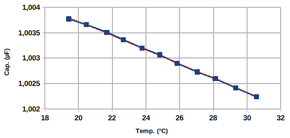
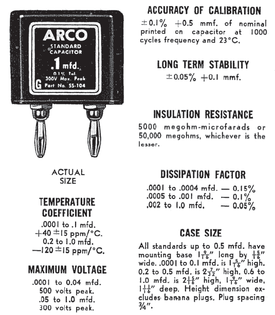
ARCO SS-series capacitors
These oldtimers surface once in a while on the second hand market, and they appear to have been popular for some calibration work. References to the series do occasionally appear in the literature, and Andeen-Hagerling manufactures the test fixture adapter TTA1 which accepts both the Arco SS-series and General Radio type 1409 capacitors. The stability of the SS-series is not stellar, and the temperature coefficient for each capacitor definitely has to be found in order to put it into use for calibration. For instance, the temperature coefficient of the 1 µF model SS-105 in my lab is larger than specified. The graph on the left shows the measured capacitance for the SS-105 under ovenized conditions. The temperature was measured with a Pt100 sensor and the AOIP PN 5207, and the capacitance was measured by a Quadtech 7400 at 1 kHz. The average temperature and capacitance were found over a period of at least 1 hour after at least two hours of acclimatization. The calculated temperature coefficient, based on the linear fit, is -139.6 ppm/K. The data sheet promises -120 ±15 ppm/K. |
