Modifying the DK-3060 KX 10-9 S for 225 kHz operation

Pictures to be added.
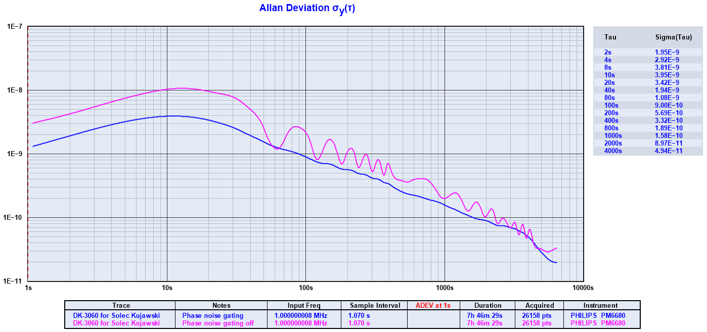
The ADEV is clearly improved by gating out the phase modulation (blue = with gating, purple = without gating). The frequency measurements were done during daytime to avoid the influence of trajectory disturbances.
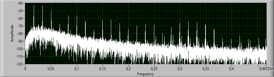
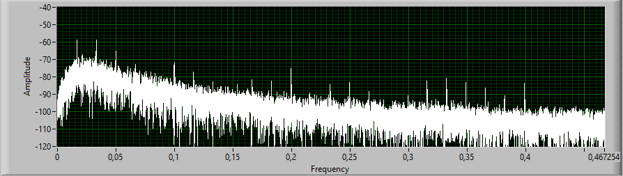
An FFT of the frequency data shows a significant reduction of the changes with one minute period (and harmonics thereof) by applying the phase gating filter circuitry. At one minute period the reduction is about 17 dB.
|
The receiver was originally made for the Kalundborg longwave transmitter in Denmark, and had been collecting dust since the frequency got relocated from 245 to 243 kHz. I salvaged the unit from the previous owner that was planning to use the enclosure for other purposes. My idea was to change the reception frequency from 245 to 225 kHz to have a dedicated receiver for the Polish service at Solec Kujawski.
Documentation on these receivers is difficult to obtain, but reverse engineering is quite straightforward. At first, I had some help from the service manual of a similar model, the KX 10-9 DI, though the two models differ on a few details. Later, I managed to retrieve a copy of the original manual from one of the previous owners of the company. The modification was basically about changing the intermediate frequency from 5 kHz to 25 kHz, and included these steps:
Having done this, I felt encouraged to make a few other changes to improve the behavior:
The specific model I got included an ovenized crystal oscillator working on top of the standard oscillator. However, the ovenized oscillator had been dismantled, and I decided to remove it alltogether. My first priority was to ensure proper operation of the basic circuitry before having things complicated by a dubious oven oscillator. The receiver has two separate supplies, one 5 V supply for the receiver and the standard oscillator, and one 10 V for the ovenized oscillator. The unit had separate transformers which I replaced with one, new toroidal transformer with separate windings. The 10 V supply now powers the IF stage with 10 V rather than 5 V to allow room for the cascoding. |
