EM Electronics N1a update
|
The N1a from EM Electronics is one of the few low-noise nanovoltmeters around. It is based on the traditional chopper principle, but with the important enhancement in form of a transformer which couples the chopped signal to the first amplifier stage. This can be used to lower the equivalent noise from the amplifier drastically. EM specifies the input noise of the N1a to equal that of a 60 Ohm resistor. To get lower you will have to take a look at some of their more recent models, such as the P13a with an input noise equivalent to a 0.25 Ohm resistor.
|
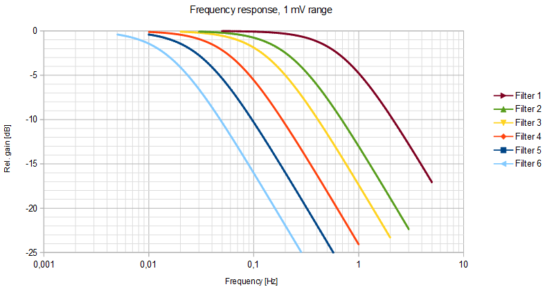
The graph above shows the frequency response for the filter settings 1 through 6. The test was done for the 1 mV range and with 1:1000 attenuator setting, using an NI USB-4431 as network analyzer. Note that for the most sensitive ranges an additional pole will start to dominate, thereby shifting the cut-off down.
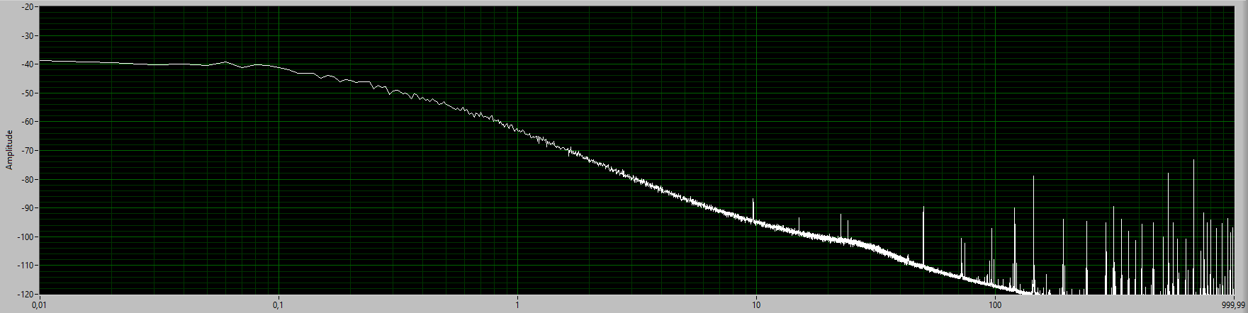
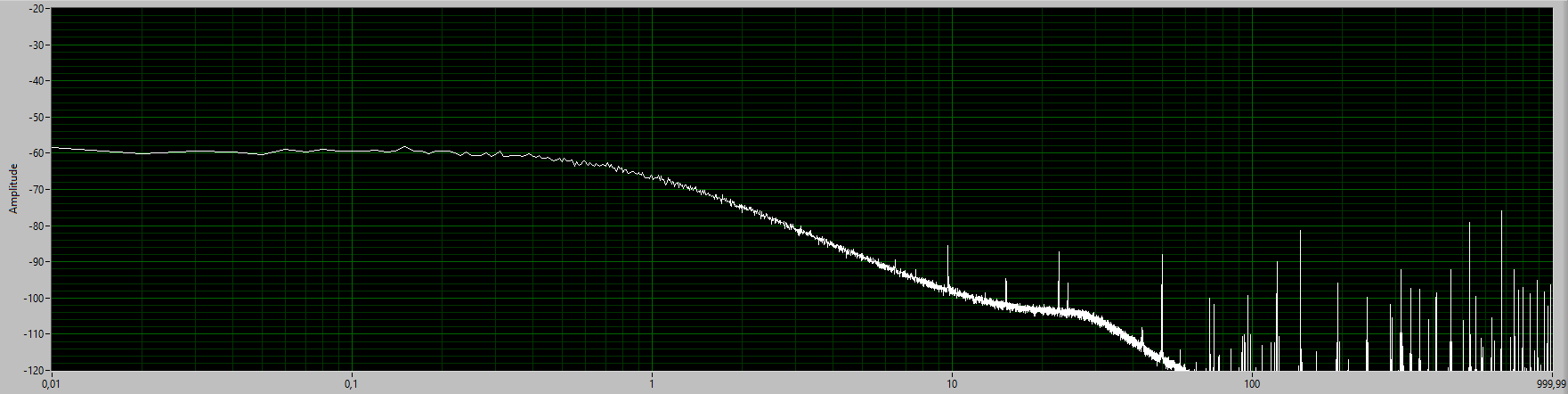
Output noise spectrum of the EM N1a, for the 10 nV range (top) and the 100 nV range (bottom), each with filter setting = 1, from 0.01 Hz to 1 kHz and with shorted input. The level is dB relative to 1 V RMS. Click on the pictures for a higher resolution.
Note how the spectrum rolls off at a lower frequency for the 10 nV range; For especially the two most sensitive ranges the cut-off for a filter setting is lowered, which may need some attention if the N1a takes part in feedback loop. The bin size of the FFT used here is 0.01 Hz, with a rectangular weighting window. The input noise density is calculated to be 1.02 nV/√Hz for the 10 nV range, and 1.06 nV/√Hz for the 100 nV range. The equivalent noise resistance for the 10 nV range is calculated to be 63.9 Ω, and thereby slightly higher than the specified 60 Ω. |
The N1a is an early model from EM Electronics, and the unit shown here was delivered from the factory in 1988. There were a few items that had to be mended: The terminals on the back broke by just inserting a banana plug, and had to be replaced. The 10-turn dial for the offset adjustment had fell apart and had to be replaced.
The unit had not been in use for a longer period of time, so the two 8.4 V batteries that had been installed by the previous owner could no longer be charged and were removed. The batteries were size PP9 (RS 229-059), and these were actually too large to fit properly inside the N1a. Sadly, the manual of the N1a does not provide any details on which batteries to use. The more common size PP3 batteries can be used, provided that R28 on the isolator board is increased from 120 Ohm to 820 Ohm to lower the charging current. Also, the operational time with size PP3 batteries will be much shorter. The current draw is about 18.5 mA, which would allow 8 - 9 hours operation with a fully charged 200 mAh size PP3 battery. As a final remark, the IC3 of the post amplifier is a TL071CP, and this device adds too much drift and offset errors at the lowest gain settings of the N1a. Replacing it with an LT1012CN8 provides lower offset, less temperature drift, and makes offset trimming of this stage unnecessary. The trimmer RT3 was removed as the LT1012 requires that the offset trimmer is connected to the positive rail, not to the negative as the TL071CP. A similar change could likely be carried out for the isolator circuitry, which uses TL061CP as input and output amplifiers. |
