Oscillator comparison
Whatever project related to timing or clocking you engage in you should know your frequency source and object to control. Below you find a small variety of different oscillators (VCXOs, OCXOs, LCOs, etc.) and how they measure. One good approach when you get a new OCXO, for instance, is to measure the frequency over a 12 or 24 hour period to capture both the warm-up period and the steady-state operation. This may reveal details not covered by the data sheet. Further analyses include phase noise and temperature dependency. Some of the measurements below focus on the frequency vs. time as this is central for deciding how to use an oscillator in a tracking receiver.
HP OCXOs

|
All of the following were measured over 24h against Z3805A after at least 24h power-on. The Fluke 6680B measured the time difference once per second between the 10 MHz from the Z3805A and the 10 MHz from the reference output of the DUT.
It's remarkable how stable the OCXO in the 5334A actually is; There's a slight frequency offset, but it remains rather constant. One reason is that the 5334A, when not in use, is left in stand-by mode practically 24/7, which has a soothing effect on any OCXO. (Pictures to be added...) |
Isotemp OCXO 91-30 (5 MHz)
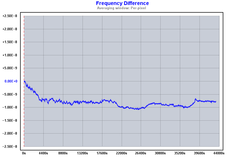
The measurements were made with open frequency control input. The power supply was the Agilent 66312A Dynamic Measurement DC Source set to 12 V. The capture was started ½ hour after power-up. The frequency was measured with the HP 5334B with the Z3805A as reference. The behavior of the 91-30 is somewhat typical for AT-cut OCXOs.
The graph suggests that the steady-state appears about 2 hours after power-up.
The graph suggests that the steady-state appears about 2 hours after power-up.
MTI Milliren 260-0624-C (5 MHz)
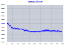
The measurements were made with frequency control input shorted to GND. The power supply was the Agilent 66312A Dynamic Measurement DC Source set to 12 V. Again, the capture was started ½ hour after power-up. Note the significantly smaller frequency deviations compared to the Isotemp OCXO 91-30.
When looking at the graph this 260 unit also needs about 2 hours before it enters the nice, steady-state operation.
The MTI Milliren 260 deserves a counter with a higher resolution than offered by the HP 5334B. A follow-up with the HP 53310A Modulation Domain Analyzer is shown below.
When looking at the graph this 260 unit also needs about 2 hours before it enters the nice, steady-state operation.
The MTI Milliren 260 deserves a counter with a higher resolution than offered by the HP 5334B. A follow-up with the HP 53310A Modulation Domain Analyzer is shown below.
This session was made with the HP 53310A with the Z3805A as reference. The data from the 53310A was captured with LabVIEW. The MTI 260 was powered on for 12 hours before making the measurement.
The 1 pps from the Z3805A was used as trigger for the Ext Arm input of the 53310A. The settings of the 53310A were 80 mHz span, 53 ms sampling (to avoid spurious modulation) and 50 ms/div time base. The average for each 1 pps tick was gathered for 40 ks. The data was processed using Ulrich Bangert's Plotter.
The 1 pps from the Z3805A was used as trigger for the Ext Arm input of the 53310A. The settings of the 53310A were 80 mHz span, 53 ms sampling (to avoid spurious modulation) and 50 ms/div time base. The average for each 1 pps tick was gathered for 40 ks. The data was processed using Ulrich Bangert's Plotter.
Vectron CO231T4Y (5.0112 MHz)
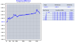
This in an older TCXO which I intend to use for down-mixing of two 5 MHz sources in order to make phase comparisons at about 11.2 kHz rather than at 5 MHz. This TCXO provides TTL level output and runs at 5V. The graph shows the frequency over 1 hour, after 12 hours of operation.
The measurement was made with HP 5334B, TimeLab V1.2, National Instruments GPIB-USB-HS, with Z3805A as reference.
The measurement was made with HP 5334B, TimeLab V1.2, National Instruments GPIB-USB-HS, with Z3805A as reference.
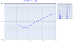
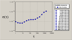
This is the corresponding Allan Deviation for the Vectron CO231T4Y.
Morion OCXO MV85 C20F-5V-SIN (10 MHz)
|
|
This compact (25 x 25 x 12.7 mm) OCXO runs at 5V and is destined to replace experimentally the XO in the Truetime 60-TF. A frequency tripler followed by a division by 5 will provide the required 6 MHz for the divider chain of the 60-TF. The objective would be to decrease the loop bandwidth in an effort to improve the stability. Another advantage of using an OCXO like this is that I can get 10 MHz out from the 60-TF in addition to the present 1 MHz.
|
HCD71 in LM Frequency Reference
|
The UK based Securicor Radiocoms Ltd. once manufactured a "Linear Modulation Mobile Radio System" in which a separate frequency reference box provided the required 10 MHz reference. Though a very rare device, the service manual with schematics is actually available on the internet (search for "LM-220-rptr-svc-man.pdf"). The manual reveals that the reference box features the HCD71 OCXO plus output buffers and power supply. There's no readily available external voltage control, but there's a trimmer on the back panel to set the internal tuning voltage. The leaded design and ample space allow modifications, however, should you get the inclination.
A word of caution, however: About half an hour after I powered up the frequency reference up the very first time, the mains filter started to emit a crackling sound, followed by a badly smelling column of smoke. This was not the first time I had encountered a burn-out in a mains filter, by the way. Some mains filters appear to be highly unreliable, I would recommend that you replace the mains filter as a preventive measure should you come across one of these otherwise nice references. The graph shows the ADEV over 24 hours after 24 hours of power up (to be added). |
More analyses to follow...
