Pulse and high-speed
The pulse pages cover high speed design, sampling oscilloscope techniques, pulse generation and the like.
- Pulse generator line-up
- Tunnel diode pulse driver
- The comb generator
- Oscilloscope line-up
- Sampling techniques
- 3G-SDI measurements
Pulse sources
Tektronix Type 284 Pulse Generator
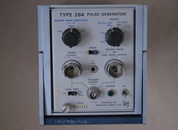
The 284 is a tunnel-diode pulser that produces rising edges with a specified rise time of 70 ps or less. The fixed repetition rate of the pulse is about 50 kHz. The 284 has a convenient pre-trigger output with selectable pre-trigger time to allow triggering of a sampling oscilloscope. The 284 also includes a square wave generator with period of 10 us, 1 us and 100 ns, and a sine wave generator with 10 ns and 1 ns period.
The service manual is available on the BAMA site at http://bama.edebris.com/manuals/tek/284/, and a description of an educative repair session is found at http://www.amplifier.cd/Test_Equipment/Tektronix/Tektronix_other/284.html
Note: You need to search for General Radio adapters and a power cable for the 3-pin power connector to use the 284 (good luck)...!
|
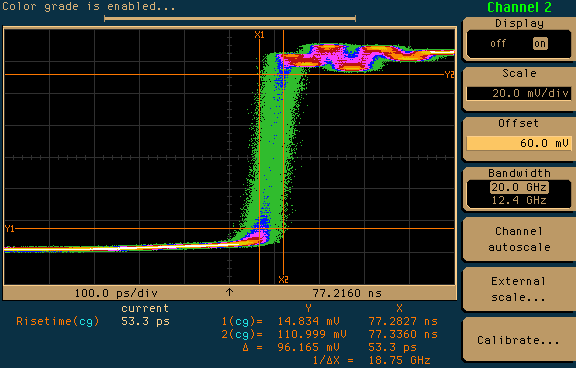
A while ago I got a second 284, a scrapped unit with a dead pulse output. I was tempted to jump to the conclusion that someone had fried the tunnel diode. However, it turned out that the tunnel diode was in great shape, but the trigger circuitry was simply no longer able to trigger it. I had to increase the bias current for the tunnel diode by adjusting the supply rail from the specified 20 V to 20.8 V, and by adding a 10 kOhm resistor in series with the TD bias potentiometers R132 and R133.
The picture on the left shows the pulse from this unit right after the modification of the TD bias, captured with the Hewlett Packard 83480A oscilloscope + 83485A sampling module. With a bandwidth of 20 GHz and 17.5 ps rise time, the calculated rise time of the pulse from the 284 is about 50 ps, well below the specified maximum of 70 ps. The 284 was connected to the input of the 83485A through a GR-274 to SMA (m) adapter, a 6 dB attenuator from Omni-Spectra specified to 18 GHz, and an SMA to 3.5 mm adapter. The 83480A was triggered by the trigger output of the 284. In this measurement, the jitter is fairly high, and may require further adjustment of the snap-off current for diode D165, as described in the service manual. |
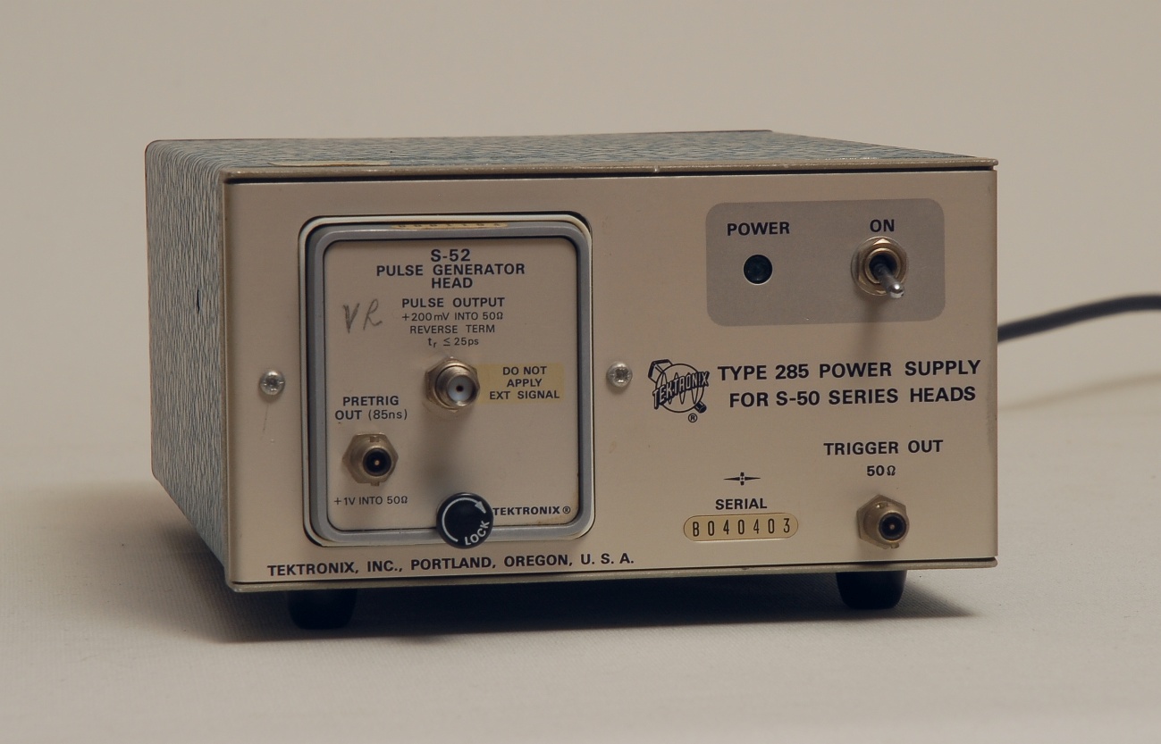
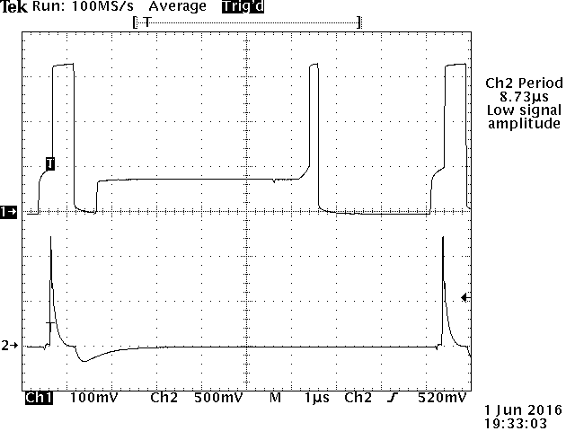
Tektronix S-52 Pulse Generator Head with Type 285 Power Supply
|
The S-52 plug-in excels with its 25 ps rise time, making it one of the fastest pulse generators that have been commercially available, even faster than the Type 284 above. The pre-trigger output provides the necessary pre-delay to allow a sampling oscilloscope to observe the leading edge. An annoying detail is the rare BSM connector used for the trigger output: You need to find an original Tektronix 012-0128-00 BSM to BNC cable (10"), alternatively the 012-0127-00 BSM to BNC cable (18"), or to find an adaptor. In the end, you may run out of patience and replace the BSM connector with something more common, typically SMA.
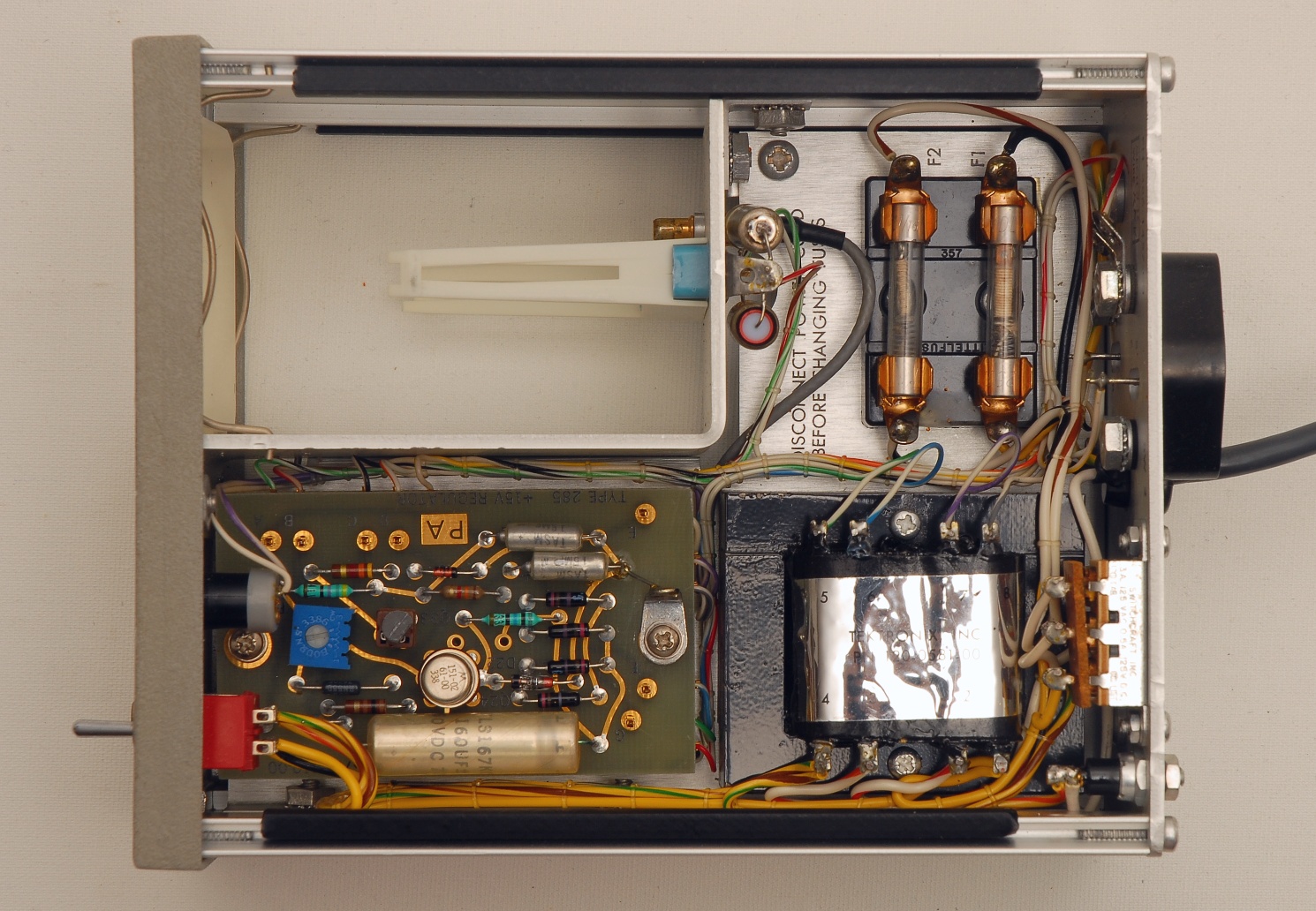
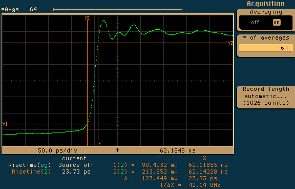
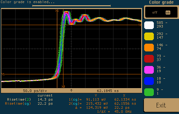
Powering the S-52 is also an issue. The S-52 plug-in was designed for the 3S and 7S families of sampling head compartments, which also provide power. A convenient power source is the hard-to-find Type 285 Power Supply, shown in the picture. Without a sampling head compartment or the Type 285 you will need to make an adaptor to power the S-52. The circuit-board of the S-52 mates with a Tektronix 131-0581-00 12-pin female connector, but alternatives are available, such as the Cinch 50-12A-30 (Farnell 1608539). In the bottom row the first picture shows a full period of the output pulse, where Ch1 is the pulse output, and Ch2 is the pretrig output. Only one of the rising edges is preceeded by the trigger signal. The center and right pictures show the rising edge as seen on the Hewlett Packard 83480A oscilloscope + 83485A sampling module, at full 20 GHz bandwidth, connected to the S-52 through 4 cm semi-rigid cable and a 6 dB attenuator. Rise time for the averaged and the color grades picture is measured to 23.73 ps and 22.2 ps, approaching the specified 17.5 ps rise time of the 83485A. For a service manual of the S-52 and of the Type 285 refer to the TekWiki pages http://w140.com/tekwiki/wiki/S-52 and http://w140.com/tekwiki/wiki/285. |
|
|
|
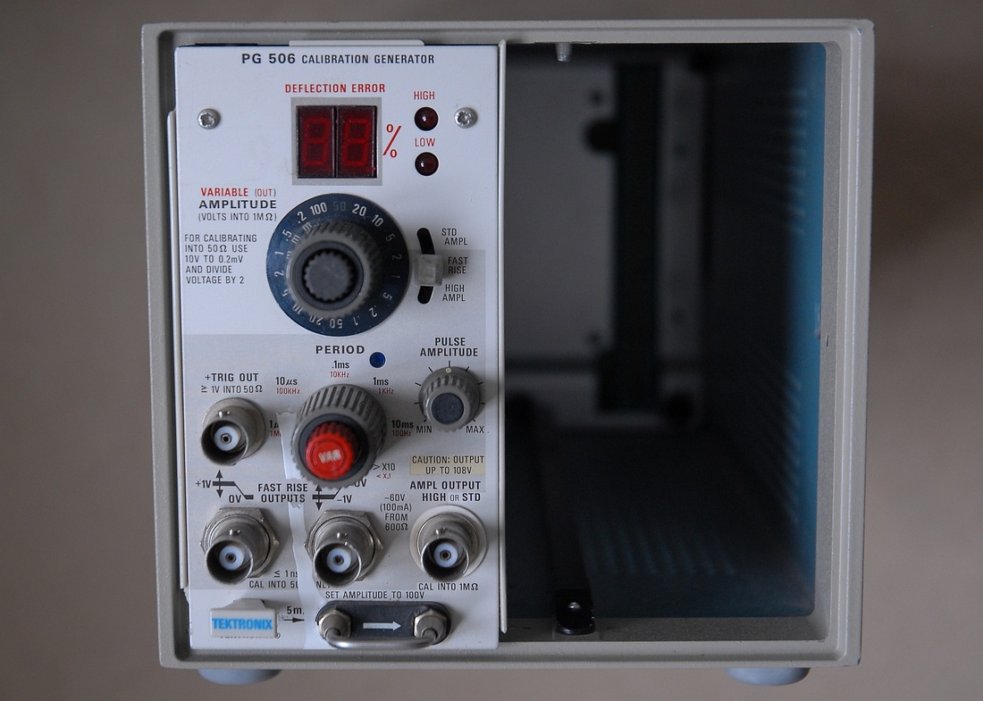
Tektronix PG506 Calibration Generator
|
This plug-in for the Tektronix TM5xx series power modules is intended for calibration and adjustment of oscilloscopes. It features a pair of fast-rise square wave outputs, and a separate output for "standard" or "high" amplitude square waves. The generator also provides a 5 mA DC or 1 kHz square wave current loop for calibrating current probes.
The standard amplitude mode provides a 1 kHz square wave at selectable levels with a specified level accuracy intended for amplitude calibration. The high amplitude mode provides square waves with adjustable frequency and level. Only typical levels have been specified for this mode, but there's a specified maximum for the leading edge aberrations. The fast-rise mode provides negative and positive going square waves with a specified maximum transition time of 1 ns. Both the leading edge aberrations and the flatness have been specified for this mode. The available output level allows the PG506 to drive the Tektronix 067-0681-01 Calibration Fixture (see below). The PG506 does not have sufficient level to guarantee operation of the 067-0681-01 below 125 Hz, however. |
|
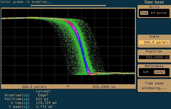
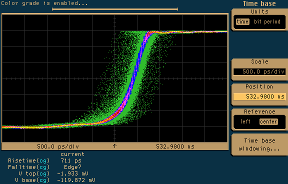
The fall time of the positive-to-zero signal is close to 750 ps and the rise time of the negative-to-zero signal is about 850 ps, observed on the Philips PM3400 sampling oscilloscope, which has a specified transition time of 200 ps. This suggests that the fast-rise outputs are indeed faster than specified. Having seen these figures I got encouraged to make further checks with the Hewlett Packard 83480A oscilloscope + 83485A sampling module.
On the 83480A/83485A the 10/90% fall time and rise time are 622 ps and 711 ps respectively, according to the automatic transition time calculations in the color grade display mode. A 6 dB attenuator was located at the output of the PG506, and another at the input of the sampling oscilloscope. The cable was 1 m of RG58. The figures on the left show some jitter due to the fact that the trigger event takes place half a cycle before; The trigger output of the PG506 provides only 8 ns pre-trigger for the fast-rise mode, whereas the 83480A/83485A requires at least 22 ns pre-trigger to allow observation of the trigger event. For a service manual of the PG506 refer to the TekWiki pages at http://w140.com/tekwiki/wiki/PG506 or the BAMA site at http://bama.edebris.com/manuals/tek/pg506/ |
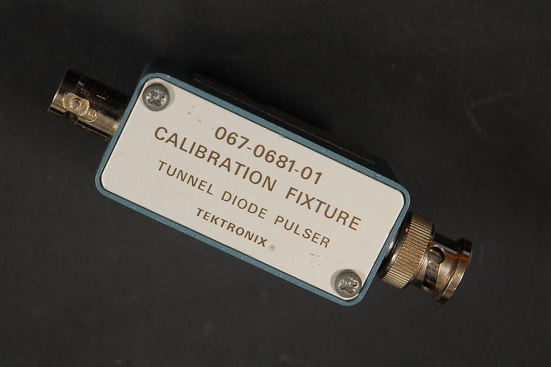
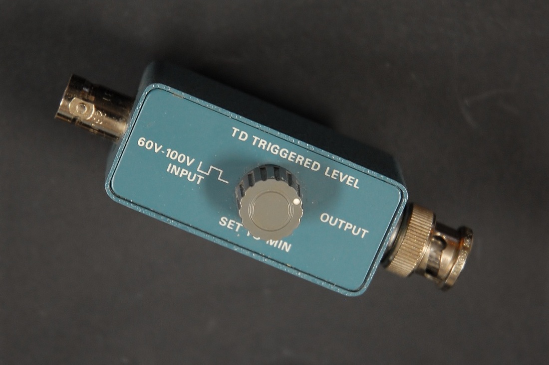
Tektronix 067-0681-01 Calibration Fixture
|
This device is a small tunnel-diode pulser that requires an external pulse generator to trigger the diode. The voltage swing of the pulse generator has to be about 60 V to 100 V (!) to ensure correct operation. The specified rise time of the calibration fixture is 125 ps or less. Note that there are significant time variations between the input and output edges. For that reason, the calibration fixture is primarily useful for testing ordinary oscilloscopes that do not require a separate trigger input, rather than sampling oscilloscopes.
The calibration fixture was originally intended to be used with existing Tektronix pulse generators, such as the Type 106 or the PG506 Calibration Generator (see the description above). Generators that can deliver the required amplitude are not commonplace. I have made a pulse generator box that delivers the required voltage to put the calibration fixture into use at other frequencies than provided by the PG506. A diagram is shown below. For further information on the 067-0681-01 including a manual refer to the TekWiki pages http://w140.com/tekwiki/wiki/067-0681-01 |
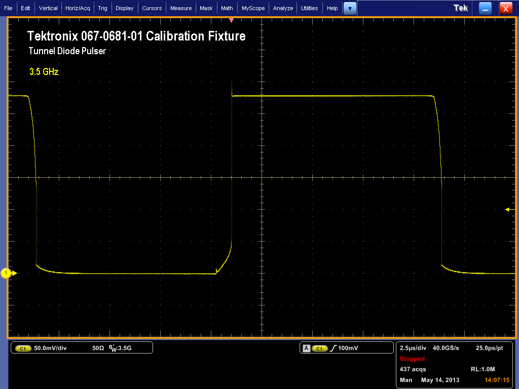
This is a full 50 kHz cycle from the Tektronix 067-0681-01 Calibration Fixture, terminated in 50 Ohms by the oscilloscope, a Tektronix DPO7354.
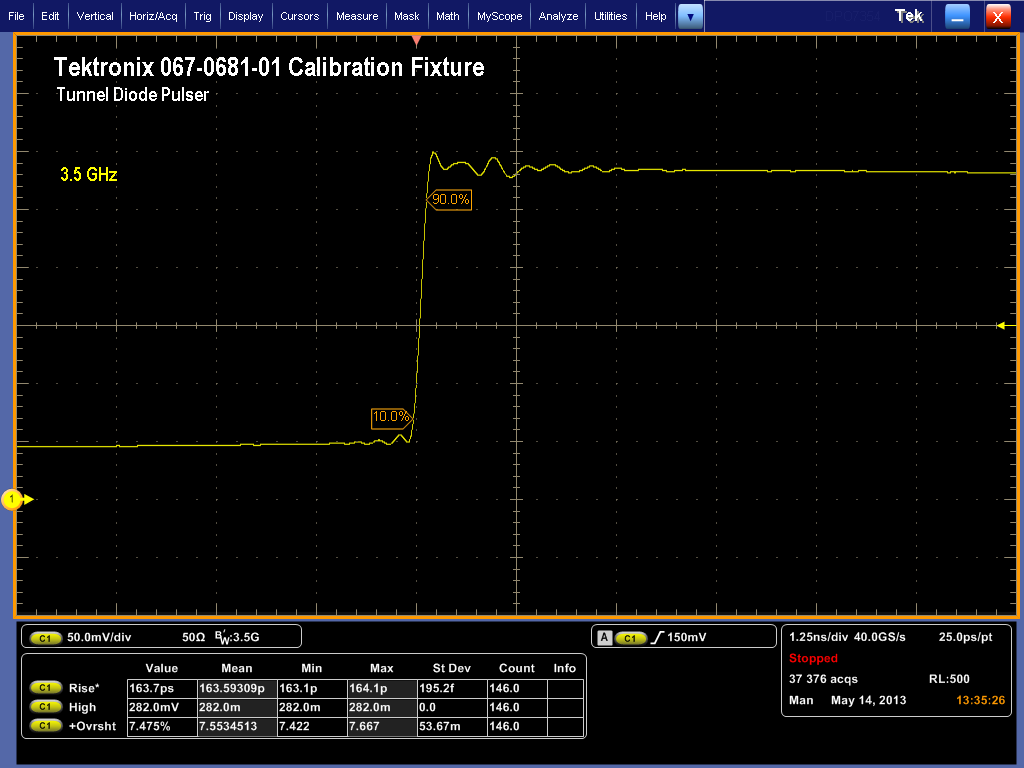
The picture shows a close-up of the rising edge from the 067-0681-01 seen on a Tektronix DPO7354 oscilloscope with 3.5 GHz bandwidth. The calibration fixture was connected directly to the BNC connector of the oscilloscope, with the input impedance set to 50 Ohms.
With a specified rise time of 115 ps for the DPO7354 the rise time of the signal from the calibration fixture is calculated to (163.6 ps ^2 - 115 ps ^2) ^0.5 = 116 ps, which is better than the specified maximum of 125 ps.
The step has an amplitude of 230 mV.
With a specified rise time of 115 ps for the DPO7354 the rise time of the signal from the calibration fixture is calculated to (163.6 ps ^2 - 115 ps ^2) ^0.5 = 116 ps, which is better than the specified maximum of 125 ps.
The step has an amplitude of 230 mV.
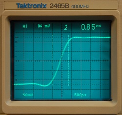
The 2465B shows 850 ps rise time with the 067-0681-01, resulting in some 842 ps rise time, conveniently below the specified 875 ps, when compensating for the 116 ps rise time of the 067-0681-01.
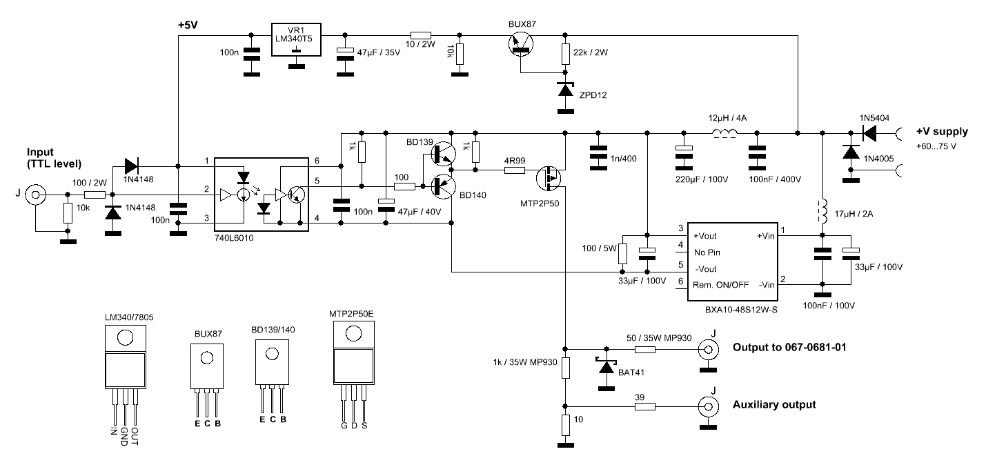
This is the schematic diagram of the pulse power stage I use to trigger the 067-0681-01 calibration fixture if I need other frequencies than those provided by the PG506.
You connect an ordinary pulse generator with 5 V amplitude to the input, and the output provides a pulse with an amplitude determined by the power supply. I use a 2 x 30 V supply to get 60 V amplitude, which is sufficient for reliable triggering. When the optocoupler drives the gate of the P-channel MOSFET down the output is pulled high.
The switch-mode supply was a model that was readily available in the drawer to produce the -12 V referred to the high-voltage rail, but you may prefer other solutions to provide the required rails in your implementation. I took care to keep the connections short to minimize the inductance in an attempt to produce clean edges so that the generator may be used for other purposes than just triggering the calibration fixture.
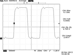
Hewlett Packard 8082A Pulse Generator

The rise/fall time of the 8082A is about 1 ns, which is an order of magnitude slower than the tunnel-diode pulsers above, but the 8082A allows you to vary the pulse repetition rate, the rise/fall time and the output level over a wide range. As a general-purpose pulse generator and for the characterisation of many circuits, the 8082A is a helpful tool.
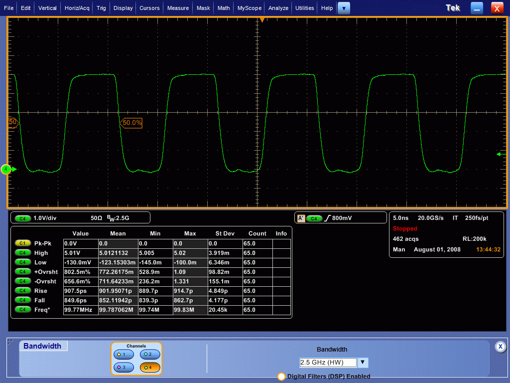
This shows the pulse from the 8082A at 100 MHz rate and 5 V amplitude when captured by the Tektronix DPO7354. The 8082A was connected via a short 50 Ohm BNC cable (about 30 cm) to the input of the oscilloscope, set to 50 Ohm input impedance.
The measured rise time is 902 ps, and fall time 852 ps. Correcting for the rise/fall of the DPO7354 (140 ps @ 2.5 GHz used here), we get rise time = 891 ps, and fall time = 840 ps.
The measured rise time is 902 ps, and fall time 852 ps. Correcting for the rise/fall of the DPO7354 (140 ps @ 2.5 GHz used here), we get rise time = 891 ps, and fall time = 840 ps.
Hewlett Packard 8406A Frequency Comb Generator

The 8406A is a generator that produces a continuous train of short pulses from a Step-Recovery Diode at different repetition rates. When the signal is observed on a spectrum analyzer, you'll see a multitude of spectral lines in a comb-like pattern where the distance between the spectral lines equals the repetition rate.
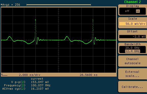
The pulses at 100 MHz repetition rate from the 8406A comb generator observed on a sampling oscilloscope (Hewlett Packard 83480A main frame + 83485A sampling module, set to 12.4 GHz bandwidth), through a 6 dB attenuator.
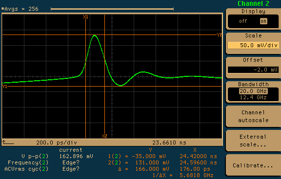
The same settings of the 8406A output, but the oscilloscope set to 20 GHz bandwidth and 200 ps/div. The pulse width of 176 ps suggests a cut-off frequency about 5.7 GHz.
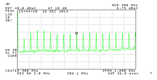
This is the resulting spectrum, seen on a Hewlett Packard 8591C spectrum analyzer with 1800 MHz span, at 100 MHz repetition rate. The output amplitude was set for the flattest response. A 12 dB attenuator was connected to the output of the 8406A, and a 6 dB attenuator was connected to the input of the 8591C.
The screen dump was made through RS232 by PrintCapture.
The screen dump was made through RS232 by PrintCapture.
Philips PM5715 Pulse Generator
The PM5715 is a general-purpose pulse generator for the laboratory. It features directly accessible controls of repetition time, delay and duration, and has adjustable transition times for leading and trailing edges, much like the Hewlett Packard 8082A. The transition time is specified for a maximum of 6 ns, with less than 5% aberration. The 8082A is obviously faster, but the PM5715, on the other hand, covers lower frequencies and higher amplitudes than the 8082A.
The picture shows the pulse response for an 8.1 MHz square wave captured with the Tektronix TDS340A 100 MHz oscilloscope using 1 m RG58 cable terminated with 50 Ohm. When compensating for the specified 3.5 ns transition time of the TDS340A, we get about 5.0 ns transition time for the PM5715. In comparison, the rise and fall time readings observed with the Tektronix 2465B 400 MHz oscilloscope read 5.1 ns, which again gives a transition time of 5.0 ns for the PM5715 when compensating for the specified 875 ps transition time of the 2465B.
The picture shows the pulse response for an 8.1 MHz square wave captured with the Tektronix TDS340A 100 MHz oscilloscope using 1 m RG58 cable terminated with 50 Ohm. When compensating for the specified 3.5 ns transition time of the TDS340A, we get about 5.0 ns transition time for the PM5715. In comparison, the rise and fall time readings observed with the Tektronix 2465B 400 MHz oscilloscope read 5.1 ns, which again gives a transition time of 5.0 ns for the PM5715 when compensating for the specified 875 ps transition time of the 2465B.
Hewlett Packard 54118A Trigger
|
|
The 54118A is intended to widen the trigger range of oscilloscopes to 18 GHz. The input frequency is specified to the range between 500 MHz and 18 GHz, but the 54118A can operate at lower frequencies (100 MHz or so). The trigger output frequency is quite low, between 5 and 20 kHz. The trigger pulse has about 220 mV amplitude and is about 5 ns wide. No rise time or aberration specifications were published for the 54118A, so I use the 54118A to assist the 83480A sampling oscilloscope for input frequencies above 2 GHz.
(Picture to be added). |
Philips PM9590 transition time converter
|
|
Transition time converters (TTCs), also known as risetime filters, are typically used to slow down the edges from fast pulse generators with a fixed transition time. One purpose could be to reduce issues with reflections, another could be the need to apply a proper edge rate for a logic family. A traditional low-pass filters will also slow down a fast pulse, but TTCs focus on pulse fidelity and on the return loss for each port. For this very reason, the design of a TTC would typically include lossy elements (resistors). For further reading take a look at application note AN-7a from Picosecond Pulse Labs and at patent US5491367 granted in 1996 to Hewlett-Packard. The latter reveals a structure much similar to a cascade of diplexers.
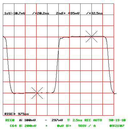
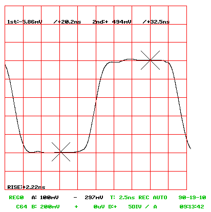
TTCs are available from companies like Keysight, Picosecond Pulse Labs (Tektronix), BitifEye, and Barth Electronics, Inc., but Philips once offered the PM9590, designed to increase a transition time from 1 ns to 2.4 ns. The effect is demonstrated on the figures on the left: They show the pulse from a 8082A pulse generator running at about 44 MHz, and set to minimum transition time, captured by the Philips PM3340 sampling oscilloscope. On the rightmost figure the PM9590 is introduced in the signal path, and the transition time measured by the PM3340 goes up from 975 ps to 2.22 ns. |
