Source showcase and comparison
The timing/frequency sources in my lab include:
There are excellent sources on the web that cover the technology behind the different sources (GPS / rubidium / OCXO, etc.) and the advantages/disadvantages of each. Below, you'll find supplemental information about the sources that you may find helpful, in particular if you belong to the time-nut community.
The antenna for the Rapco and Hewlett Packard GPS receivers is a Symmetricom 58532A Reference Antenna, which is connected to an active 1:4 splitter, the model S14WI from GPS Source. This setup ensures a proper signal level for all the GPS boxes.
- Efratom LPRO-101 rubidium
- Rapco 1804M GPS Precision Frequency Source
- Rapco 1804L5b GPS Precision Frequency Source
- Rapco 1804L26 A1 GPS/Rb Precision Frequency Source
- Hewlett Packard Z3805A GPS time and frequency reference receiver
- Hewlett Packard 5061B Cesium Beam Frequency Standard (tube now run flat)
- Own DCF77 analog reference design
- Time service ensemble receiver
- Symmetricom 090-03827-01 Timing Receiver
- Hewlett Packard, Oscilloquartz and MTI-Milliren OCXOs
- Stanford Research Systems FS700 Loran-C frequency standard (standard version and option 01)
- Telecom Solutions Digital Clock Distributor Local Primary Reference
- Spectracom 8160A NBS Frequency Standard Receiver (modified)
- True Time model 60-TF WWVB Frequency Comparator (modified)
- Box 73 DCF77-gesteuerten 10 MHz Frequenznormal (modified)
- Halcyon Electronics Off Air Frequency Standard OFS-1 (modified)
- DK-3060 Instruments KX 10-9 S (changed from 245 kHz to 225 kHz operation)
- Trak Systems 8821E-20 GPS Clock
- Hopf 6039 DCF77 PCI Funkuhr
There are excellent sources on the web that cover the technology behind the different sources (GPS / rubidium / OCXO, etc.) and the advantages/disadvantages of each. Below, you'll find supplemental information about the sources that you may find helpful, in particular if you belong to the time-nut community.
The antenna for the Rapco and Hewlett Packard GPS receivers is a Symmetricom 58532A Reference Antenna, which is connected to an active 1:4 splitter, the model S14WI from GPS Source. This setup ensures a proper signal level for all the GPS boxes.
Rapco 1804M / 1804L5b / 1804L26 A1
I have a collection of three different 1804 models from Rapco Electronics, Ltd., a UK-based company which got acquired by Orolia SA, or rather by Orolia's Spectracom business unit, in 2009. The 1804 series was discontinued by Spectracom in 2013, but can occasionaly be found on the second hand market, sometimes at favourable prices.
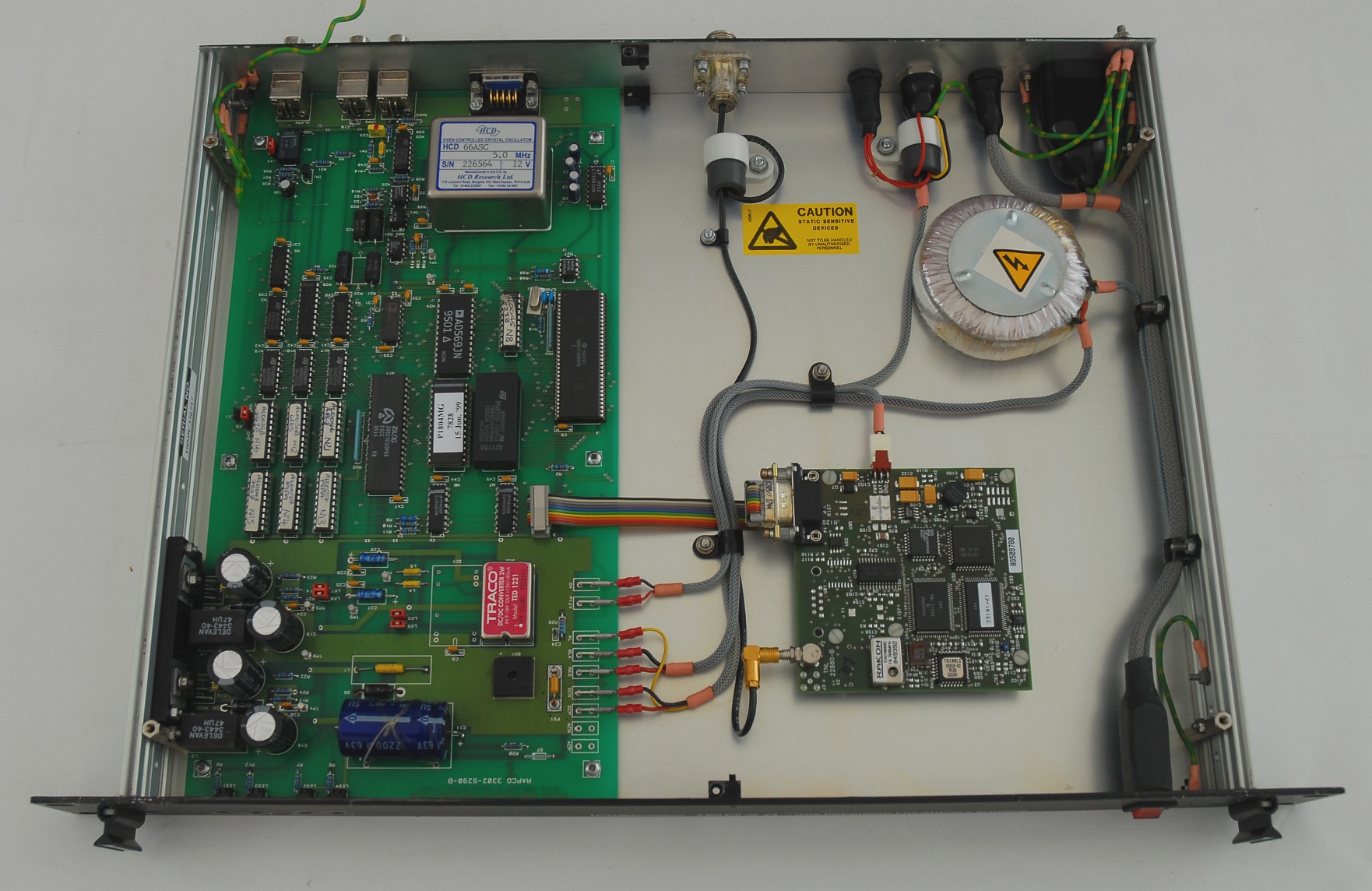
Above: The Rapco 1804M
|
The Rapco 1804M is a not-so-modern (but nicely built) GPS frequency reference, with an HCD66 5 MHz OCXO. Though the performance is far from stellar, especially when compared to later models, it is more than adequate for a range of applications, and the build of the 1805M with leaded components favours those that would like to make experiments.
I use David Taylor's 1804M Signal Monitor & Logger to monitor the state of the 1804M. Check out his site at http://www.satsignal.eu/ntp/Rapco-1804M-notes.html |
|
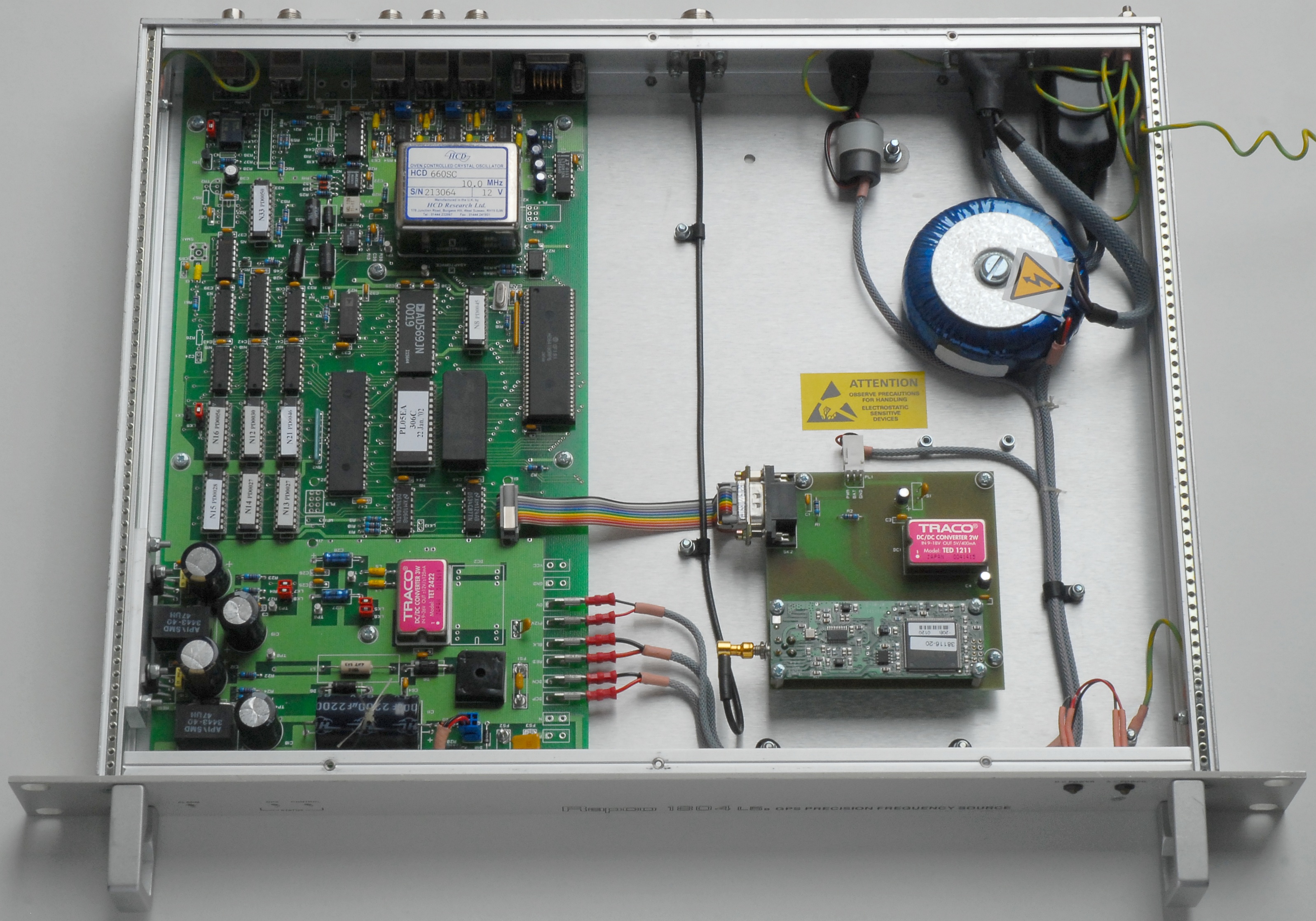
The 1804L5b is another nicely built GPS frequency reference from Rapco, based on the HCD660SC 10 MHz OCXO and on what seems to be the 8-channel Trimble Lassen SK-2 receiver. The date codes suggest that the unit was made in 2002.
You may also use David Taylor's 1804M Signal Monitor & Logger for the 1804L5b. The program shows the status of all 8 channels though it was designed originally for the 1804M. You only need to disregard that the indicator in the title bar is not green during correct operation, one reason being that the 1804L5b does not have 'coarse' and 'fine' operational states as the 1804M, but merely a 'Control' operational state. |
|
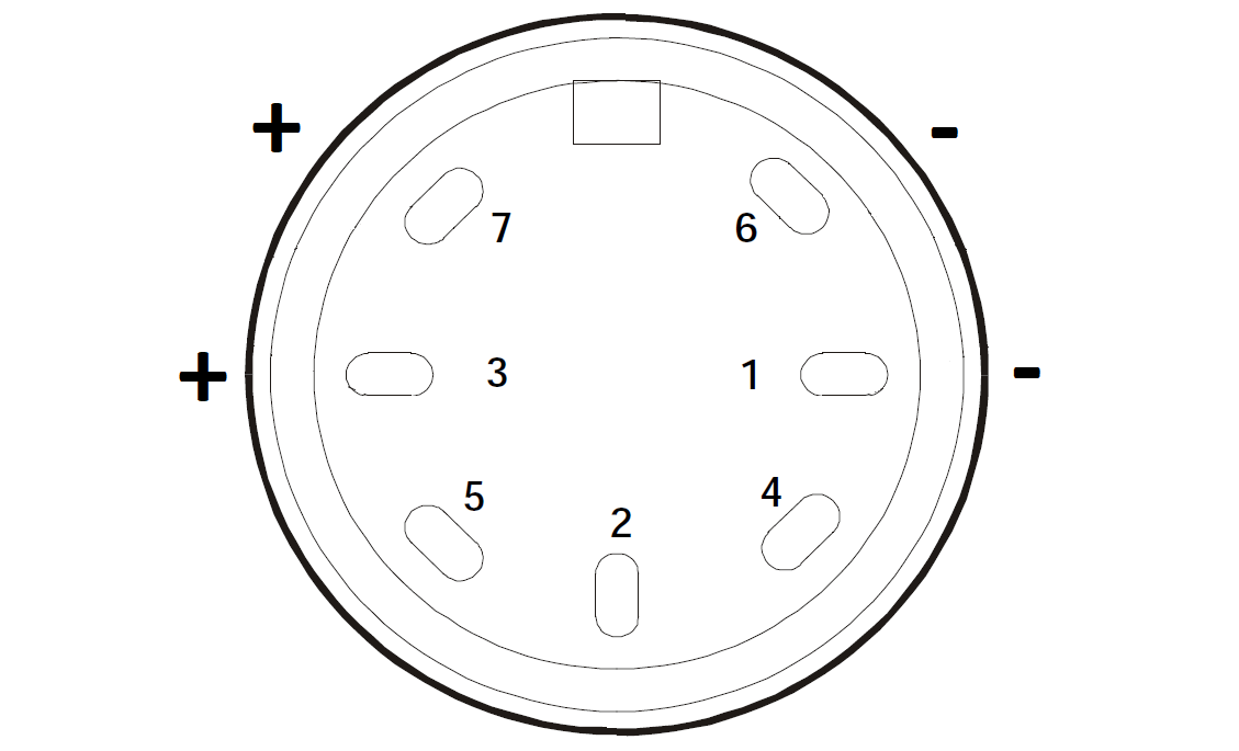
The 24 V DC input mates with a 7-pole DIN type male connector, such as Neutrik/REAN NYS323. The drawing shows the connector on the 1804 as viewed from the outside of the box. There are two positive and two negative (GND) pins. The same pin-out applies to the 1804L26.
|
|
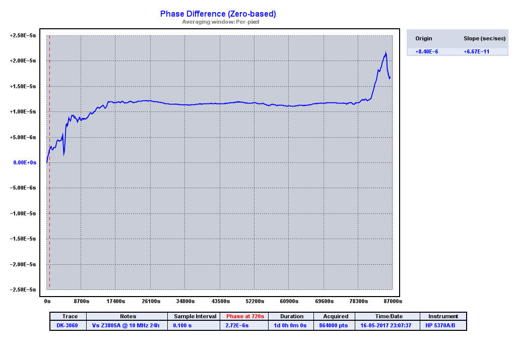
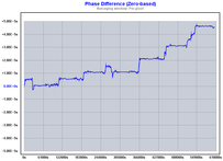
The graph shows the output frequency phase relative to the 10 MHz output from the Hewlett Packard Z3805A over one week for the Rapco 1804M and 1804L5b, measured with the Fluke 6680B and TimeLab V1.2. A frequency doubler was used for the Rapco 1804M as it provides a 5 MHz output. There is definitely a difference in the behavior between the two generations, and it appears that Rapco did a major change in the control algorithm at some point from the 1804M to the 1804L5b.
|
|
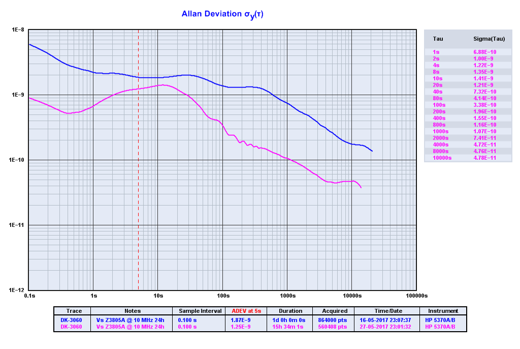
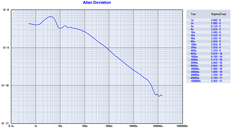
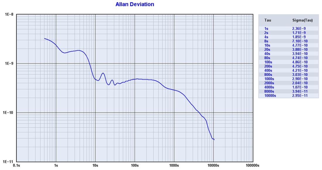
This is the resulting ADEV for the Rapco 1804M and 1804L5b, measured against the Z3805A. The newer 1804L5b is far better than the 1804M, though they have similar performance in the 100 s to 1 ks interval. The 1804L5b is better than the 1804M by an order of magnitude above 10 ks.
For short observation intervals the 1804L5b aligns with the intrinsic ADEV of the PM6680B, whereas the 1804M stays slightly above which could lead one to assume that the 1804M has worse short-term phase noise performance than the 1804L5b. Further investigations would be required to shed light on that. |
Other measurements of the 1804M reveal that the change of frequency slope coincides with updates of the code for the DAC and with the 200 ns phase jumps of the 1 pps signal. I have no manuals for the 1804M / 1804L5b models, but only for the 1804L17 and 1804M3 models. The manual for the 1804L17 states that "Once the CONTROL STATUS indicator is on, there will be no more phase-jumps in the 1Hz Timing signal, all further adjustment to maintain UTC alignment being achieved by 'steering' the oscillator frequency." This is in line with the observations of the 1804L5b.
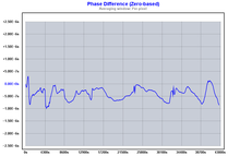
According to the manual for the 1804L17 drift-corrections take place at intervals of 512 seconds once the 1804L17 is in its 'Control' mode. By examining the data dump from the 1804L5b these DAC updates take place at intervals of 256 seconds, however. When zooming in on the phase for the 1804L5b there's a clear footprint of corrections taking place at regular intervals, and that also explains the wobbly look of the ADEV curve for the 1804L5b above 1ks intervals. The period is not 2 times 256 seconds, however. More analyses will be added below to check out the correlation between the DAC settings and the phase.
Preliminary investigations suggest that it would have been beneficial with finer voltage steps in the regulation, but the 16-bit resolution of the AD569JN DAC used in the 1804L5b puts a limitation to that.
Preliminary investigations suggest that it would have been beneficial with finer voltage steps in the regulation, but the 16-bit resolution of the AD569JN DAC used in the 1804L5b puts a limitation to that.

This is a closer look at the 10 MHz phase changes and the DAC updates in the Rapco 1804L5b. David Taylor's 1804M Signal Monitor & Logger was used to acquire logging data, and a LabVIEW application was made to parse the values and time of the DAC settings. The phase data was imported from TimeLab.
(Picture to be inserted)
(Picture to be inserted)
A final remark on 1 pps and 1 Hz: The 1804L17 manual distinguishes between "1 pps", which is a short marker pulse that stems directly from the GPS receiver and the "1 Hz" signal, which is derived from the OCXO. An internal jumper lets you decide which signal to access on the BNC output. The "1 pps" from the 1804L17 has poor short-term behavior and will be turned off when the receiver is not locked to GPS, and "1 Hz" is recommended for all timing applications.
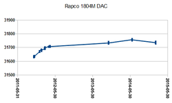
The DAC-setting changes over time due to aging and environmental changes. Recurrent monitoring during operation will tell if we're approaching either of the two ends of the DAC scale. The picture shows the DAQ setting of the 1804M unit over more than 3 years of continuous operation (the latest power cycle was November 6, 2011). The data files from the 1804M were parsed by a tool made in LabVIEW and the multiple DAC/date data sets were copied into Excel. Note how the aging rate has decreased since the first months of power-on; If it remains at this rate the DAC will not saturate any day soon.
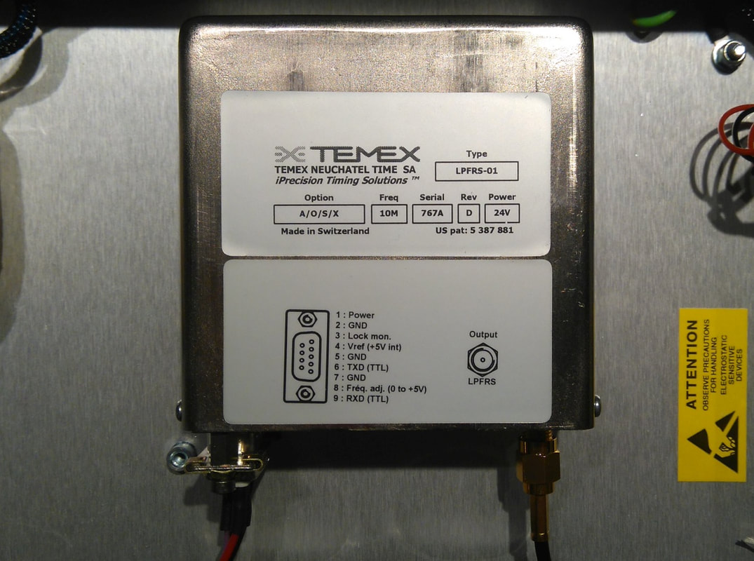
The Temex LPFRS-01 rubidium oscillator used in the Rapco 1804 L26 A21.
|
The Rapco 1804L26 A21 is the latest of the three Rapcos in my collection, and features a Temex LPFRS rubidium oscillator. It is perhaps not a huge surprise to find an oscillator from Temex in the Rapco, as Orolia, the company that acquired Rapco, was created through a spin-off of Temex’s Timing and Synchronization activities.
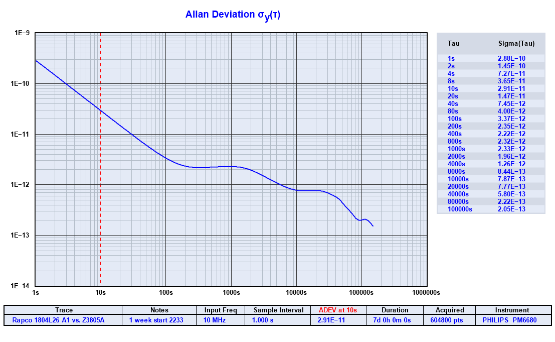
Note the date code on the devices, which suggests that the unit was made in 2007. The build looks like that of the 1804L5, and the receiver is still what appears to be a Trimble Lassen SK-2, but significant changes were made to the digital circuitry. The Temex rubidium oscillator is not a standard version but features a few options. According to the LPFRS datasheet, now available from the Orolia brand Spectratime, the letters on the label signify: Option A = Improved long term stability Option O = Analog adjustment 5 x 10e-9 ± 20% Option F = Fast warm-up Option X = Reduced harmonics, spurious and subharmonics David Taylor's 1804M Signal Monitor & Logger works for the 1804L26 A21, though the LED in the title bar remains red. The control loop of the 1804L26 is clearly designed differently compared to the 1804 models with OCXO. The DAC updates take place at a lower rate, and the 1804L26 appears to require longer time to settle after power-on, like 2 or three days, so do not expect full performance before then. One week of time interval measurement of the 1804L26 against the Z3805A (after 5 days of power-on) shows that the ADEV is significantly lower than measured for the 1804L5 from 30 s and above. At 1 ks the 1805L26 is an order of magnitude better than the 1805L5. At 100 ks the 1804L5 and the 1804L26 are comparable with an ADEV around 2 to 2.5 * 10E-13. With this level of ADEV one cannot clearly identify the contributions from the Z3805A and the 1804L26. A better test of the stability would be to compare the 1805L26 with something inherently more stable than the Z3805A, or perhaps to compare three sources, of which one should be the 1804L26, and then make a three-cornered hat analysis. Should I get around to do such a measurement I will post the results here. |
Hewlett Packard Z3805A GPS Time and Frequency Reference Receiver
You may find different variants of the Z3805A GPS reference on the second-hand market. Check out the Time Nuts archives and other resources on the net. The model in my lab has a 6-channel GPS receiver and a 10811-type OCXO. It receives the GPS signal from the Symmetricom 58532A Reference Antenna through the active S14WI 1:4 splitter from GPS Source.
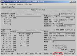
One thing to watch out for is that the control voltage may eventually approach the full scale of the regulation. This screenshot from Symmetricom's StatSat application shows that my Z3805A started to report an EFC error. Simple diagnostics queries reveal that the EFC voltage is now above 90% of full scale:
Sent: :DIAG:ROSC:EFC:ABS?
reply: +1000578
Sent: :DIAG:ROSC:EFC?
reply: +9.08451E+001
When the voltage is within 5% of the limit the Z3805A will set a hardware alarm. Before then, I need to re-calibrate the coarse adjustment of the OCXO.
Sent: :DIAG:ROSC:EFC:ABS?
reply: +1000578
Sent: :DIAG:ROSC:EFC?
reply: +9.08451E+001
When the voltage is within 5% of the limit the Z3805A will set a hardware alarm. Before then, I need to re-calibrate the coarse adjustment of the OCXO.
SRS FS700 Loran-C Frequency Standard
Despite the US decision on closing down Loran-C it's still in operation in the Northern parts of Europe. Loran-C and its modernized upgrade, the Enhanced Loran (eLoran), have received much interest by authorities that have grown increasingly concerned about the vulnerability of global navigation satellite systems (GNSS), such as GPS. In July 2013 it was reported that the General Lighthouse Authorities of the UK and Ireland will roll out eLoran along the South and East coast of the UK. According to the eLoran Definition Document from the International Loran Association, the "change to eLoran will not prelude the continued use of legacy Loran-C receivers, but legacy users will not benefit from the additional data channnel channel...". Hopefully, FS700 owners in these parts of the world should remain happy for some time to come.
In Denmark, where the lab of yours truly is located, we were fortunate enough to have the Loran-C transmitter on Sylt, a German island, as neighbor, but this site closed down. The Sylt site gave a nice noise margin up to 40 dB. Now, the two FS700 receivers run GRI = 6731, and the noise margin has dropped to typically 15-18 dB. The most annoying part, however, is that the FS700 receivers are now more prone to go out of lock.
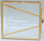
Most of the screenshots below were made using a simple loop antenna with 8½ windings of 0.5 mm2 wire on a 45x45 cm wooden frame. I use a loop antenna rather than the active whip antenna that originally came with the FS700. The simple "Antenna Termination Adapter" shown in the FS700 manual is inserted between the loop antenna and the FS700 antenna input. As my lab is located only about 250 km from the island of Sylt I never introduced further filtering or amplification, but now, in view of the weaker signal, I'm considering a Bessel bandpass to mimic the filtering of the original whip antenna.
For the permanent installation I made a larger loop antenna with 4 windings of 2.5 mm2 wire on a 80x80 cm wooden frame and a grounded base pre-amp (see the pictures further below). With this antenna I get about 15 - 16 dB more signal than the simple 8½ winding loop. This 80x80 cm antenna produced an excellent noise margin of 40 dB when receiving the Sylt station, but 15-18 dB is what I get now with GRI = 6731.
In Denmark, where the lab of yours truly is located, we were fortunate enough to have the Loran-C transmitter on Sylt, a German island, as neighbor, but this site closed down. The Sylt site gave a nice noise margin up to 40 dB. Now, the two FS700 receivers run GRI = 6731, and the noise margin has dropped to typically 15-18 dB. The most annoying part, however, is that the FS700 receivers are now more prone to go out of lock.
Most of the screenshots below were made using a simple loop antenna with 8½ windings of 0.5 mm2 wire on a 45x45 cm wooden frame. I use a loop antenna rather than the active whip antenna that originally came with the FS700. The simple "Antenna Termination Adapter" shown in the FS700 manual is inserted between the loop antenna and the FS700 antenna input. As my lab is located only about 250 km from the island of Sylt I never introduced further filtering or amplification, but now, in view of the weaker signal, I'm considering a Bessel bandpass to mimic the filtering of the original whip antenna.
For the permanent installation I made a larger loop antenna with 4 windings of 2.5 mm2 wire on a 80x80 cm wooden frame and a grounded base pre-amp (see the pictures further below). With this antenna I get about 15 - 16 dB more signal than the simple 8½ winding loop. This 80x80 cm antenna produced an excellent noise margin of 40 dB when receiving the Sylt station, but 15-18 dB is what I get now with GRI = 6731.
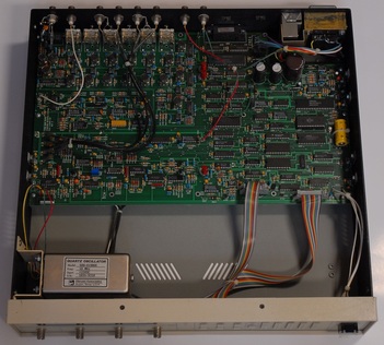
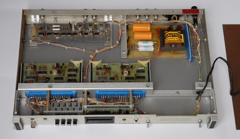
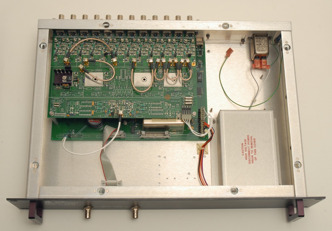
This is the interior of the FS700 Loran-C Frequency Standard. The 3rd order bandpass-filter for the input is located at the upper left, and the six LC notch filters are located along the back panel. The OCXO is the model 500-01980E from Wenzel Associates. The type numbers from Wenzel starting with 500 are custom units, so you will not likely find a data sheet on the web.
The other FS700 in the lab has Option 01 "Low phase noise oscillator" with an SC-cut OCXO which claims to provide -155 dBc/Hz @ 100 Hz, rather than -130 dB/Hz @ 100 Hz for the standard version with an AT-cut OCXO. The ADEV is stated 5x10-12 @ 1s for Option 01, and 5x10-11 for the standard version.
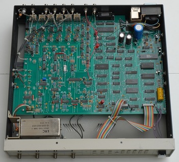
When taking a look inside we find an EROS-750-SBR-2 from ERC. Again, the web is not very helpful if you want to retrieve some specifications on this OCXO.
Note the differences between the boards in the two FS700 units: The board below is larger, and the layout of components is very different. The FS700 in the standard version has SN 00478, and the FS700 with option 01 is an older build with SN 00339.
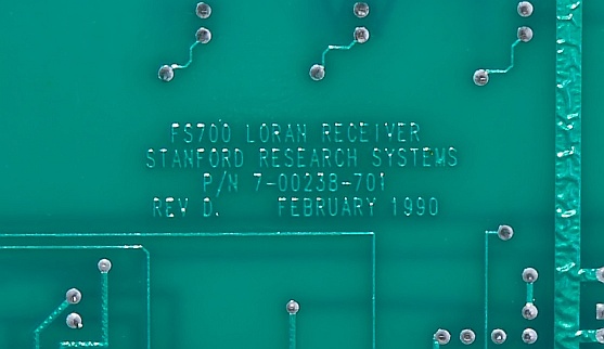
The board revision of the FS700 option 01 with SN 00339, found on the solder side.
|
The board for the later FS700 with SN 00478 is actually called FS800.
|
The FS700 was subject to some thorough changes somewhere between 1990 and 1992. On the solder side of the FS800 board the marking "43-92" indicates that the board version or production run is from week 43 of 1992
|
The defective capacitors are marked "ZS".
|
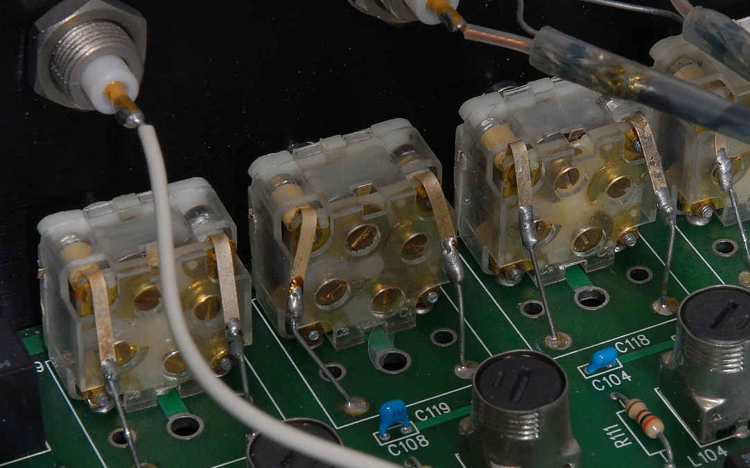
The later capacitors appear to be marked "WP" (the characters are not clearly legible).
|
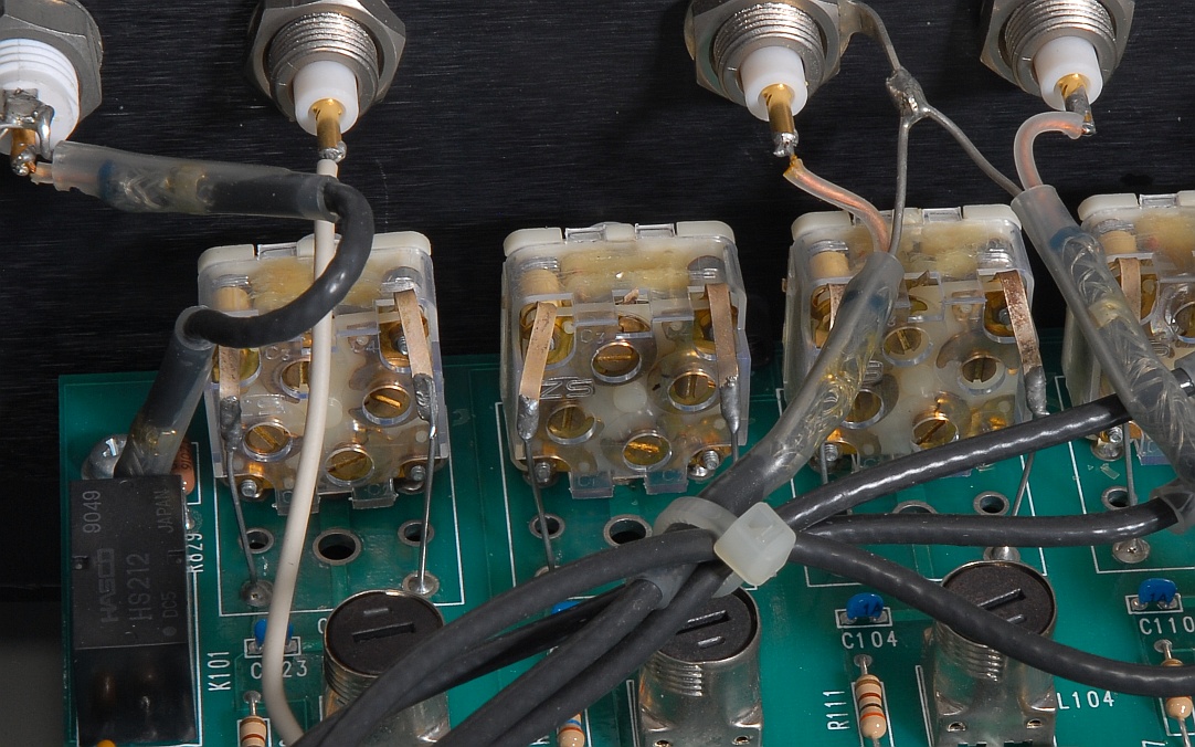
One point of concern with the older FS700 models is the variable capacitors used for the notch filters. In the old unit I got the mica of the capacitors had totally decomposed rendering the notch filters useless. In the newer version (and in the Telecom Solutions box shown below) the capacitors had been replaced with similar models that have film rather than mica as dielectric material. I have replaced the defective capacitors with similar dual gang "Polyvaricon" models and have re-tuned the notch filters according to the FS700 manual.
|
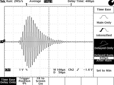
The screendump from the oscilloscope shows the LORAN Output from the FS700 using the GRI SYNCH Output as the trigger. The display of the oscilloscope was delayed 400 μs and 256 acquisitions were averaged.
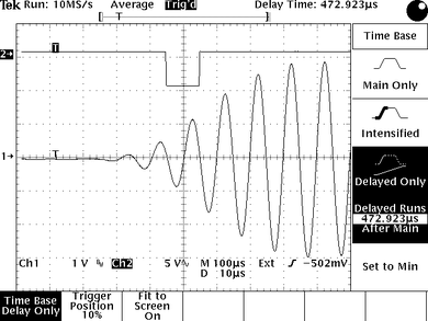
By zooming in, we can see the third zero-crossing point being surrounded by the SYNC Output signal from the FS700. As on the screendump above the GRI SYNCH Output was used as trigger, and 256 acquisitions were averaged. The display of the oscilloscope was delayed about 473 μs to position the crossing point in the middle.
|
|
|
This is the untuned 80 x 80 cm loop antenna I use to receive Loran-C and other longwave time services. A grounded base amplifier provides both low input impedance and current drive of the cable. The current draw is set to match the expectations of the FS700. The antenna is located in the attic and gives typically 38-40 dB noise margin for GRI = 7990 and sometimes even more. Up to 46 dB have been observed. For the GRI = 6731 the receiver provides about 28 dB if the reception conditions are OK.
|
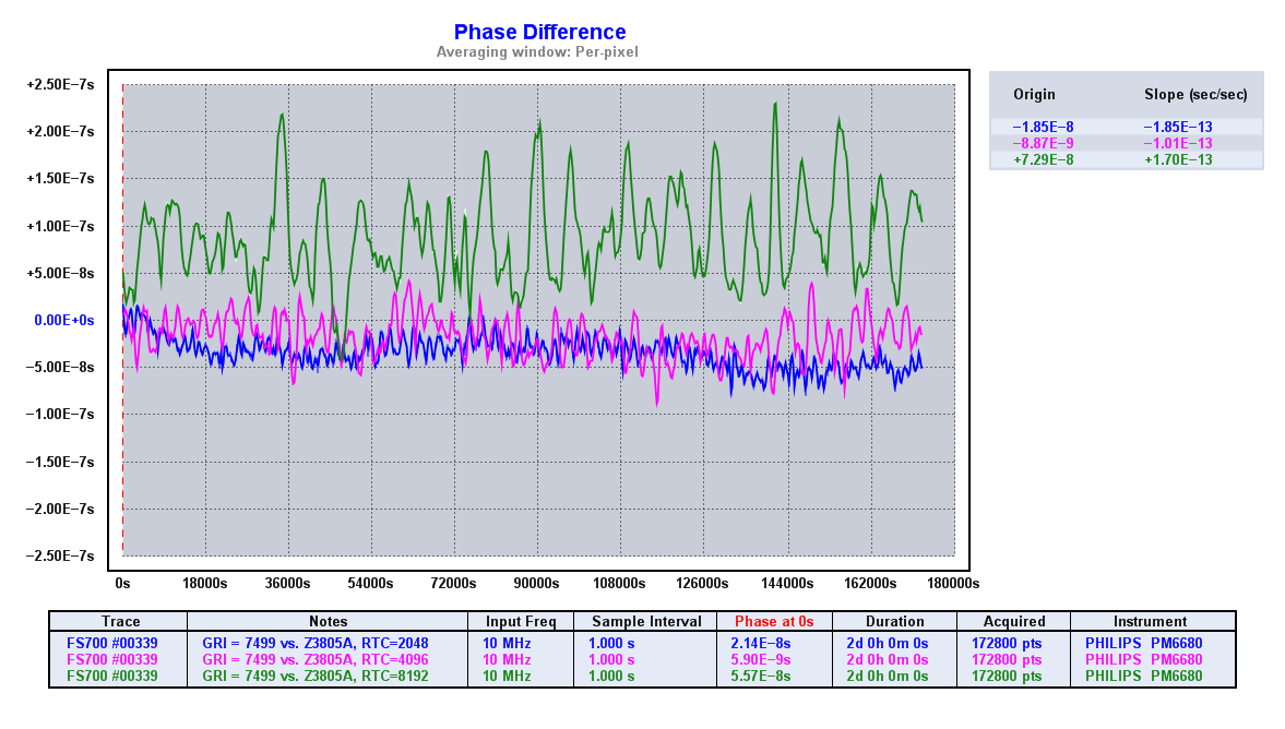
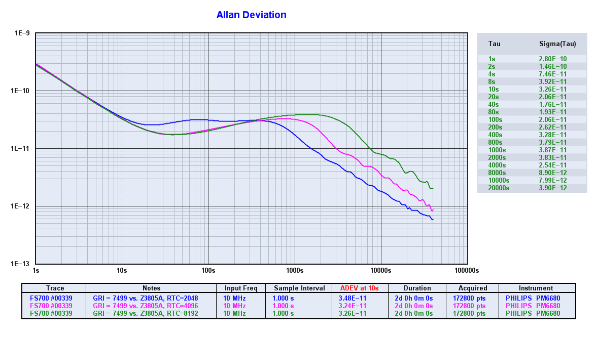
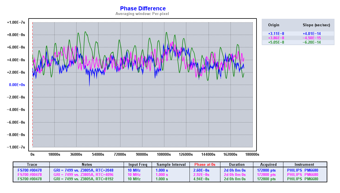
So, what's the best receiver time constant for the FS700? You can change the time constant between 128 GRI and 16384 GRI, and the FS700 manual recommends 2048 GRI with the standard OCXO, and 4096 GRI with option 1. The figures show the phase and the resulting ADEV for different time constants for each of the two FS700 units in my lab. Both receivers were set up for the same GRI = 7499, or GRI = 6731. The antenna was my 80 x 80 cm active loop antenna, the measurement time was 48 hours, and the reference in all cases was the Hewlett Packard Z3805A. The 10 MHz time interval data was acquired by the Fluke PM6680B via TimeLab. The GPIB-USB-HS adapter from National Instruments connected the PC with the PM6680B.
|
|
The figures show the phase and the resulting ADEV for time constants 2048, 4096 and 8192 GRI for my FS700 with option 1. Further analyses show that anything shorter than 2048 or longer than 4196 has a detrimental effect. Looking at the graphs, I tend to prefer a time constant of 2048 GRI over the recommended 4096 GRI.
|
|
|
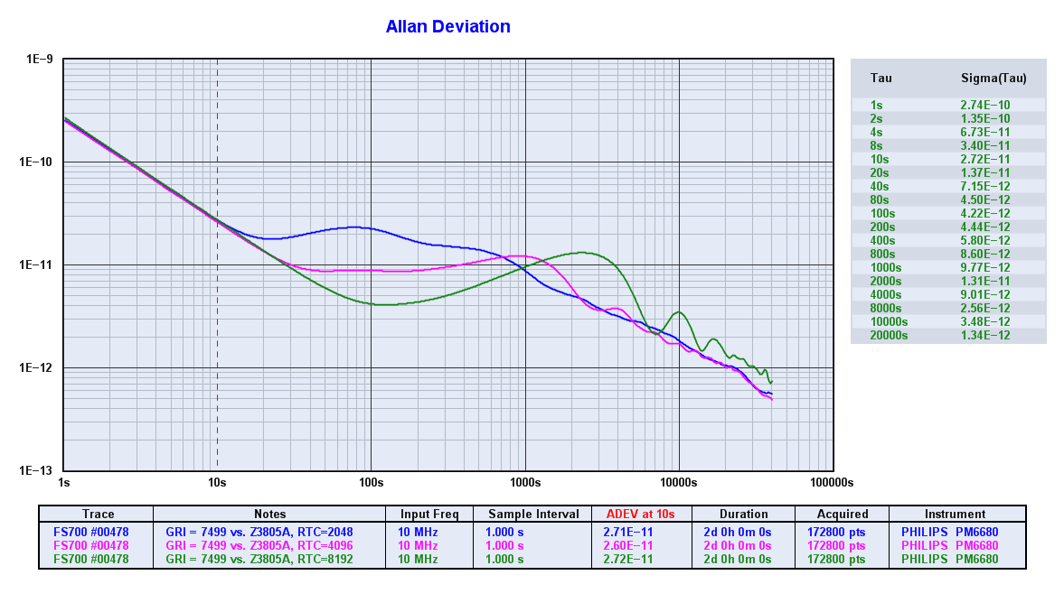
These are the results for the unit with the standard OCXO. Same GRI and measurement setup, and captured right after the measurements on the FS700 with option 1 on days with comparable weather conditions. The best receiver time constant seems to be 4096 GRI. Note the different Y-scale for the phase.
|
|
With the GRI 6731 and the much lower noise margin performance takes a hit. The graphs here show the phase and the resulting ADEV for time constants 4096, 8192 and 16384. The unit here is the FS700 with option 1. Being left with the only GRI of 6731, the FS700 needs to run with a longer time constant.
|
|
Similarly, for the FS700 with the standard OCXO, here are the phase and the resulting ADEV results for time constants 4096, 8192 and 16384.
|
To much surprise, the FS700 with the standard OCXO produces better results than the FS700 option 1. It would be fair to suspect that I mixed up the two FS700 units, but rest assured that this was not the case. I found that the results were consistent and could be reproduced.
The question remains why this is so. Is this consistent with measurements on other FS700 units? Was the OCXO in one of my two units perhaps replaced by the previous owner? How do FS700 units behave in different serial number ranges?
The question remains why this is so. Is this consistent with measurements on other FS700 units? Was the OCXO in one of my two units perhaps replaced by the previous owner? How do FS700 units behave in different serial number ranges?
|
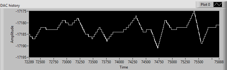
For monitoring the health of the FS700 I use a program I have written in LabVIEW to query the FS700 registers via GPIB. Files covering 24 h are automatically saved so that I may trace any events in the past. As a side effect, I also get a good picture of the ageing of the OCXO. My FS700 receiver with the standard oscillator (Wenzel 500-01980E) actually got very close to the lower control limit, so I had to carry out a coarse readjustment of the OCXO. The picture shows the DAC value for one of the two FS700 receivers over a period of one hour. The values for the 16-bit DAC (Burr-Brown PCM56P) are in the range -32767 to +32767, according to the FS700 manual.
|
Telecom Solutions Digital Clock Distributor Local Primary Reference
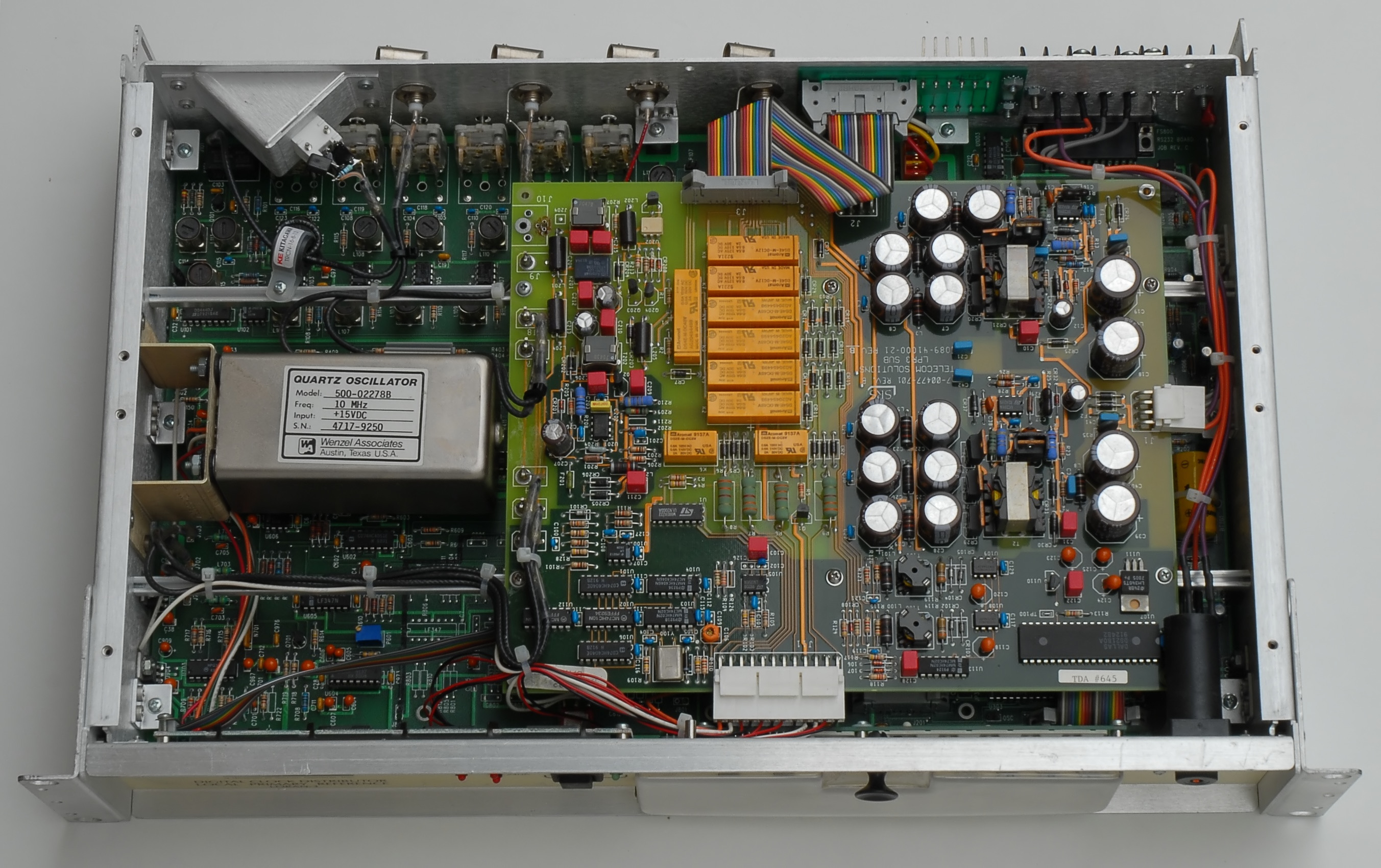
This rarely seen piece of gear is another Loran-C based frequency reference. Telecom Solutions was a division of Silicon General, Inc. This company may not sound familiar, but it changed its name to Symmetricom in 1993.
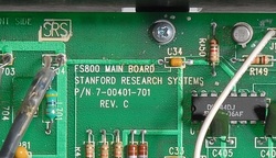
The front panel layout and details on the inside reveal that this box is a Stanford FS700 rebuilt for telecom applications. It's powered by -48 V and includes some telecom-specific interfaces on the back panel. The antenna input connector is a twin BNC, which I've replaced with an ordinary BNC connector. The receiver board is marked "FS800 MAIN BOARD P/N 7-00401-701 REV. C" on the component (top) side, and is therefore identical to the board in the FS700 above with SN 00478.
The OCXO is a Wenzel model 500-02278B. When I received the unit I had to adjust the coarse tuning of the OCXO to make the receiver obtain lock. Shortly after the first power-up it issued the warning "Osc. near end of tuning range", and then another more fatal message stated that the tuning range had actually been exceeded. The tuning voltage was at that point 0.7 V, but the frequency was 60 ppb above 10 MHz. The remedy was to lower the frequency offset by turning the coarse adjustment counter clockwise. After having done this, the receiver locked to the 74990 GRI and the tuning voltage settled at 1.447 V. More investigations will be made before I make the final adjustment of the OCXO,
|
|
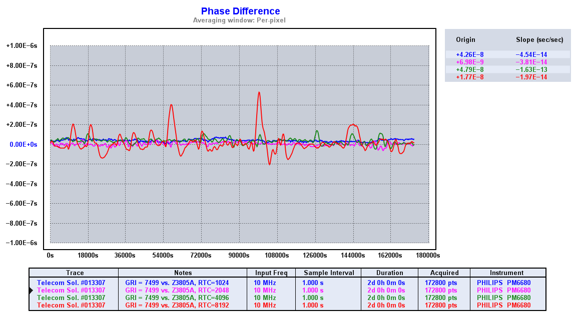
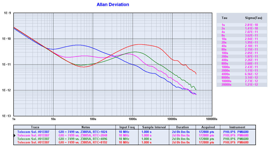
The figures show the phase and the resulting ADEV for time constants 1024 through 8192 GRI for the Telecom Solutions reference.
The measurement conditions are the same as for the FS700 above to allow comparison. |
Hewlett Packard 5061B Cesium Beam Frequency Standard
This was the lab's primary frequency reference, equipped with option 004 high performance tube. The cesium contents of the tube have been depleting rapidly, and the beam current is now close to zero, so the 5061B is only used sporadically for experiments. I guess this is how cesium standards are being used by most users without a substantial budget for tube replacements. Recurrent activation of the ion pump should prolong the life of the tube, but the tube has for a long time been destined for the inevitable cesium beam tube death. The Z3805A remains the reference workhorse of the lab.
True Time 60-TF WWVB Frequency Comparator
The introduction of bi-phase modulation for the 60 kHz WWVB service in the US rendered the 60-TF useless for its original purpose. However, it can be used with the MSF service in the UK which operates at the same frequency.
The picture shows the interior of the 60-TF before it got modified. The original design suffers from a few design flaws that had to be adressed before I could put the 60-TF into operation.
On the top of the list, there are issues related to safety: Various parts run too hot, the wiring is less than optimal, and the board with the transformer bends slightly down with the risk of soldering pads touching the chassis
The first thing I did was to rebuild the power supply for European 230 VAC and to add some robustness to the mechanical design. The modifications are described in more details on the repair pages.
As a receiver, the design features a PLL with a much too wide bandwidth. It guarantees to ruin the medium-term accuracy in an attempt to achieve long-term accuracy, all too typical for off-air receivers. Also, the design is plagued by poor low-level behaviour, including some issues with pollution of the 60 kHz input signal.
This is the interior of the 60-TF after the modification. There are elaborate changes to the chassis and power supply including a new cooling arrangement. The changes to the PLL boards, in particular to the receiver PLL board on the right, are also quite clear to see. In addition to the moving coil meter and its function switch the front panel now features a time code LED, located on the left.
An experimental acquisition help circuitry is located between the receiver PLL and the power transformer. There's also an experimental 60 kHz crystal filter located between the input module and the receiver PLL. Note also the foam that covers the 6 MHz crystal of the receiver PLL: This is essential to protect against air turbulence which otherwise ruins the ADEV, in round figures with an order of magnitude.
Modifying the 60-TF has been a truly fun and educative process, which has turned the 60-TF into a useful piece of test gear.
|
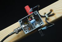
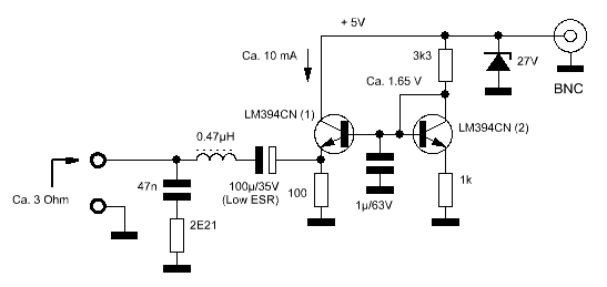
This is the simple ferrite antenna I made for the True Time 60-TF. It consumes 3 mA at 12 V supply, and is powered by the 60-TF. When not being used with the 60-TF the antenna may be powered via a splitter box. Note that the supply impedance of the 60-TF has to be reduced to prevent starving of the antenna.
The zener protects against low-energy ESD from eg. cable charge, handling, etc. The parasitic capacitance of the zener used here is of no importance; Between 5 V and 15 V the capacitance of the zener was measured to vary between 11.1 pF and 15.7 pF. The capacitors were selected to obtain resonance at 60 kHz. The resonance was found by comparing the signal from a generator being loosely coupled to the antenna, and the signal on the BNC output of the antenna on an XY-coupled oscilloscope; When the Lissajous pattern aligned for a frequency within 1% of 60 kHz the capacitance was deemed correct. |
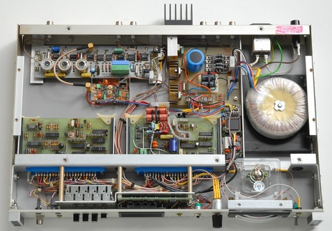
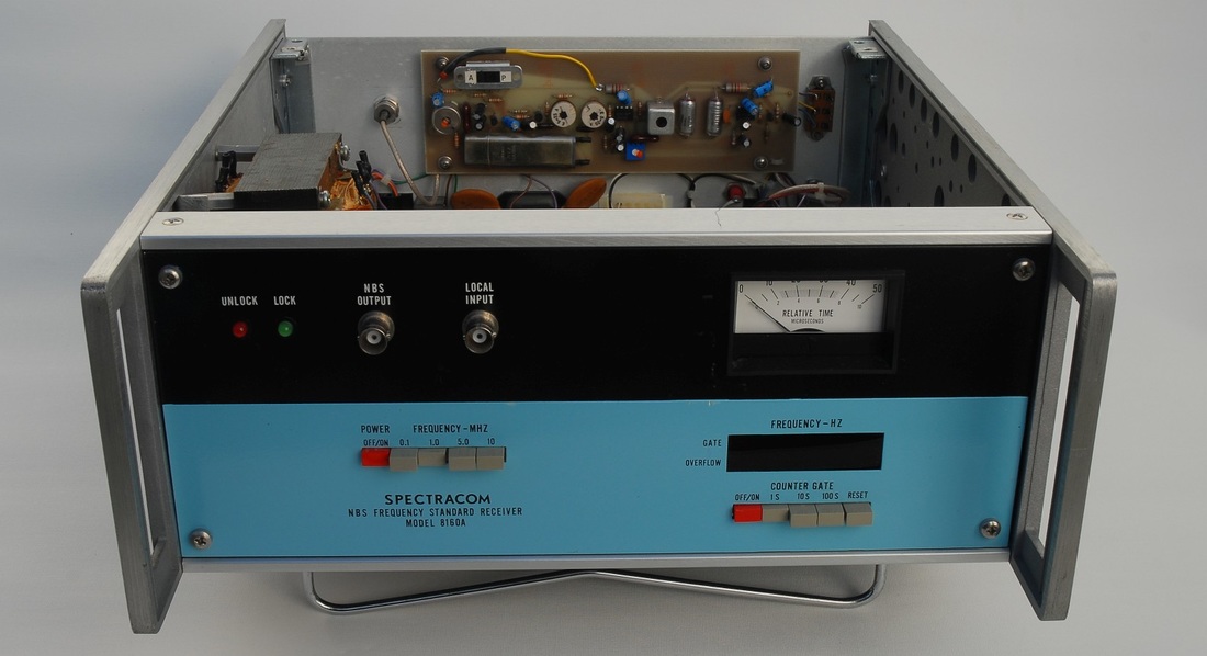
Spectracom 8160A NBS Frequency Standard Receiver
|
This is yet another off-air receiver where a PLL controls a crystal oscillator. Compared with the True Time 60-TF, the Spectracom 8160A offers a selectable 100 kHz, 1 MHz, 5 MHz or 10 MHz output, not just 1 MHz.
The receiver was designed for the 60 kHz WWVB service run by the NBS (National Bureau of Standards), hence the name. Since 1988, the NBS has been known as NIST (Institute of Standards and Technology). When NIST introduced the new modulation scheme for the WWVB service, receivers such as the 8160A became useless in the US. However, the 8160A can still be used in parts of Europe to track the MSF service. I reduced the loop bandwidth with a factor of ten, and added an acquisition aid circuitry, to boost the performance and usefulness of my 8160A. Further details are found on the repair pages. |
|
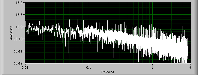
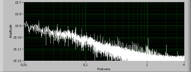
The first figure shows the ADEV for the original, unmodified 8160A and for the modified 8160A, compared at 1 MHz with the Stanford FS700 Loran-C reference and measured with Fluke PM6680B.
(To be inserted) The next two figures show the FFT spectrum of the time interval data, for the original 8160A and for the modified 8160A. Note the distinct 1 Hz contents and harmonics. You can even see the minute pattern at about 16 mHz feeding through. After the modification the performance improved significantly: Though captured on another day, for obvious reasons, there's no doubt that the overall Allan deviation has improved and that the harmonics from the time code signal are lower. The RMS level at 1 Hz is reduced from 8.85e-9 s to 8.60e -11 s, partly due to the reduced bandwidth, and partly due to a lower offset in the mixer. The RMS level at 1/60 Hz is about the same, going from 3.4e-9 s to 2.9e-9 s. A reduction of the spectrum level in the minute region would require a further reduction of the loop bandwidth. |
|
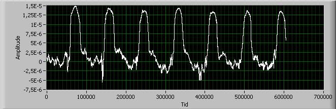
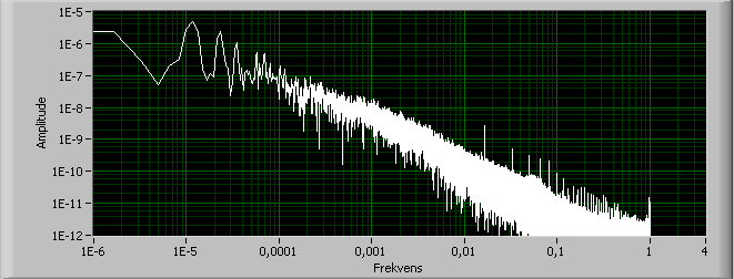
Encouraged by the results above I ran the 8160A for a week while capturing TI data against the Z3805A as reference. Comparison was done at 1 MHz, using an external 1:10 frequency divider for the Z3805A, the 5334B counter and TimeLab. The capture was done in February, 2015.
The upper graph shows the time from the 8160A to the Z3805A. A higher figure means that the recovered clock signal from the 8160A comes earlier and that the effective trajectory delay is smaller. The delay is shortest shortly after noon, local Copenhagen time. This is consistent with the amount of sunlight on the trajectory from Anthorn in Cumbria, UK, to Copenhagen. The 8160A did not go through a single cycle slip once during the week. I would feel inclined to assume that this is due to a combination of the offset reduction and favorable propagation conditions. The FFT shows an RMS level of 1.7e-11 s at 1 Hz, and 2.8e-9 at 1/60 Hz, which is better than measured previously. This suggests that the propagation conditions were better the second time. |
Efratom LPRO-101 rubidium
|
|
The LPRO is a well-known rubidium reference, frequently available on the surplus market at a decent price. Look out for the lamp voltage so you don't get an end-of-life unit. I recommend to consult the internet, which is full of information on the LPRO, including manuals.
Looking for a heat sink? Try out Fischer Elektronik SK 44/100 SA, available from eg. Farnell (4621426). The holes you need to drill for the LPRO can be positioned neatly between the fins. This heat sink also leaves you with space for eg. mounting brackets. The upper figure shows the frequency during warm-up and acquisition. Lock is obtained within ???? seconds. The lower figure shows the ADEV over 24 h after a 2 hours of operation. |
Trak Systems 8821E-20 GPS Clock
Top view of the 8821E-20
|
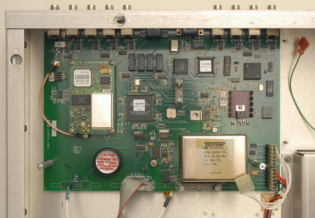
A closer look at the receiver board with the top board removed
|
This GPS receiver features an Isotemp OCXO91-17D 10 MHz oscillator disciplined by a Motorola B8121Z1116 Oncore 8-channel receiver module. A special feature of this model is the generous number of output channels, 4 times 1PPS and 4 times 10 MPPS located on the receiver board, plus 12 times 10 MHz located on the separate output board.
|
|
|
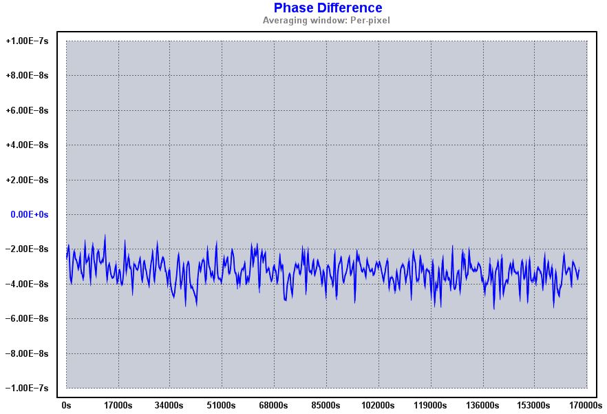
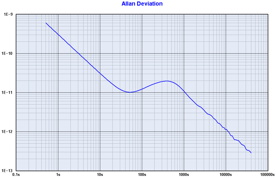
The graphs show the results from the first run with the 8821E-20 compared with the Z3805 over 48 hours, starting 24 hours after power-up to allow proper averaging af the position.
|
Box 73 DCF77-gesteuerten 10 MHz Frequenznormal
This is a neat combination of a DCF77 clock and frequency reference, available as a partly assembled kit from Amateurfunkservice GmbH. The kit is well elaborated, it includes high-quality plated circuit boards, and the assembly instructions (in German) are clear and informative.
As a frequency reference, you should not expect miracles. It is after all just a fairly simple off-air PLL receiver that controls an ordinary 10 MHz crystal. However, a few design details you can do something about (and at a modest cost) in order to improve the accuracy and usefulness:
As a frequency reference, you should not expect miracles. It is after all just a fairly simple off-air PLL receiver that controls an ordinary 10 MHz crystal. However, a few design details you can do something about (and at a modest cost) in order to improve the accuracy and usefulness:
1) The loop speed-up mechanism with its wide loop bandwidth is governed by a window detection of the voltage from the phase detector. This works at start-up, but whenever there are phase disturbances from eg. destructive fading the loop will switch mode and you'll see some huge frequency excursions. A simple improvement of the design is to introduce a circuit that prevents the loop from entering the wide bandwidth mode once it has reached the narrow bandwidth mode.
2) The bandwidth of the narrow bandwidth mode is really too wide, and should be reduced to improve ADEV. Thanks to the loop speed-up mechanism this can be done without risking an unhealty long lock time.
Details about the modifications are shown under the repair pages.
2) The bandwidth of the narrow bandwidth mode is really too wide, and should be reduced to improve ADEV. Thanks to the loop speed-up mechanism this can be done without risking an unhealty long lock time.
Details about the modifications are shown under the repair pages.
The frequency excursions during destructive fading for the original design, typically around sunset / sundown, are massive. This effectively rules out the device as a frequency reference, perhaps except during daytime and for distances to the Mainflingen transmitter site where the ground wave stays dominant.
(To be added)
(To be added)
The Allan Deviation for the original design vs. modified design during daytime only, showing the effect of the reduced bandwidth, though being measured on two different days.
(To be added)
(To be added)
The Allan Deviation for the original design vs. modified design over 48h span. Though the measurements were not done at the same time, it's clear that the bandwidth reduction and the mechanism to prevent the loop from entering the wide bandwidth mode have a clear effect. In the modified design you will encounter cycle slips, but not massive disruptions.
(To be added)
(To be added)
Halcyon OFS-1 Off Air Frequency Standard
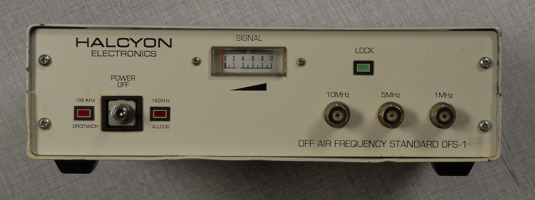
The frequency selector on the unit shown here is not the original as it had been replaced by the previous owner.
|
This rarely seen off-air frequency standard from UK manufacturer Halcyon, apparently no longer in business, is intended for the France Inter service on 162 kHz or the Droitwich transmitter on 198 kHz. The BBC may eventually phase out its longwave service, but when that happens we hopefully still have France Inter.
As an alternative to the antenna on the back the OFS-1 accepts an external signal on a BNC connector. This should be your preferred choice of operation to avoid any unwanted pick-up. Be warned that the OFS-1 is extremely sensitive to common reception anomalies, and is likely only of any value close to either of the two transmitters. In fact, I had to modify the OFS-1 in order to make it behave like a frequency reference. The details are found on the OFS-1 repair page. |
|
|
Here are the results for the time vs. GPS and the ADEV for the OFS-1 after the modification with the BBC 4 at 198 kHz as the source. The capture was made during March 2015 over a week, starting and ending at 21:00 UTC. The antenna was a tuned ferrite loop powered by the OFS-1. The typical cycle jumps (5.05 us for 198 kHz) during fadings are evident, leaving the OFS-1 with an offset of 7 cycles after a week.
The two lower graphs show the phase and the ADEV for the daytime of the last day. The phase excursion stayed roughly within 1 us, and the ADEV is better than 1e-10 for 6 s and above. There are no graphs for the original OFS-1 as these would be pointless. Even during favorable reception conditions and during daytime the original OFS-1 had great difficulties going into lock, and the frequency would typically stay at the minimum for the VCXO or it would occasionaly jump around. |
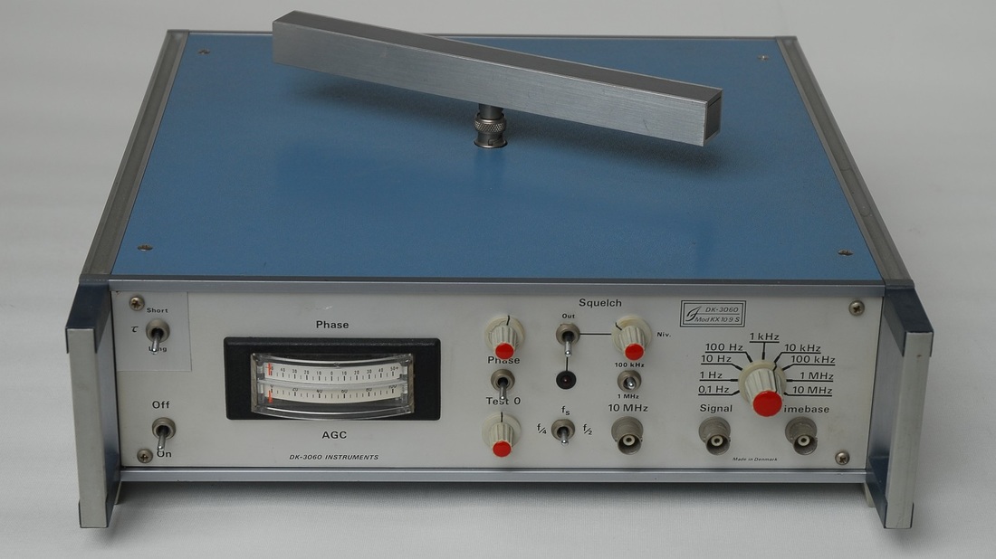
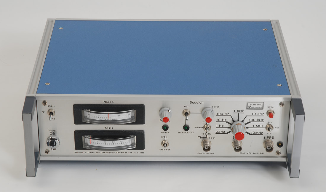
DK-3060 Instruments Mod KX 10-9 S and MFX 10-9 TSI Standard Frequency Receivers
|
The Danish company DK-3060 Instruments manufactured a range of off-air receivers. As far as I know, the models targeted DCF-77, Motala, Rugby (now MSF), and the Kalundborg broadcast service on longwave in Denmark.
The model shown here is the KX 10-9 S, made for the Kalundborg service while it was transmitting at 245 kHz. The frequency of the service was later changed to 243 kHz, which sadly turned this and similar receivers useless. With a modest effort I modified the unit to allow reception of the Polish transmitter at Solec Kujawski. Further details will be posted later under the repair pages. The next model is the MFX 10-9 TSI, made for the DCF77 service. Note that I replaced the phase meter with a model with symmetric scale at the time when I modified the circuitry so that the meter would actually show phase rather than oscillator voltage. The modification makes the adjustment of the free-running frequency by the phase knob both easier and more accurate.
Like similar receivers of this era, the stability is not impressive, and you should only put the receiver into use during daytime when a stable ground wave reception is possible. The graph shows the phase for the MFX 10-9 TSI compared to GPS on a day in May 2017 over 24 hours, starting from midnight, with typical phase excursions and wander during the dark hours. The resulting ADEV for the 24h session is shown as the blue curve. The purple curve shows the ADEV during daytime (on another day, though.) |