Repairing Tektronix TM modules
Debugging the TM modules can be very annoying. First of all, they are not only powered by the TM 500 mainframe, but the regulator circuitry is located on the TM modules while the power regulator transistors are located in the mainframe. To get access to a module during operation you need an extender cable, or to wire the module up to be powered by an external power supply. In case of the TG 501, which only needs +15 V and + 5 V, it's fairly easy to add a couple of wires to power it up outside the mainframe. Modules like the PG 506 are a bit more challenging. In that case, it's easier to simply remove the casing of a TM 500 mainframe so that a module can be powered.
Secondly, the mechanical design is not debug-friendly, to say the least. The modules are difficult to dismantle and to re-assemble. The components on the boards are difficult to access (typically only the side of a board facing one of the two sides of the module is accessible). It would be great if one of the boards had been hinged, for instance, but the boards need to stay assembled for the module to operate. In spite of the hassle the modules are still popular as they serve specific purposes, like calibration of an oscilloscope.
Secondly, the mechanical design is not debug-friendly, to say the least. The modules are difficult to dismantle and to re-assemble. The components on the boards are difficult to access (typically only the side of a board facing one of the two sides of the module is accessible). It would be great if one of the boards had been hinged, for instance, but the boards need to stay assembled for the module to operate. In spite of the hassle the modules are still popular as they serve specific purposes, like calibration of an oscilloscope.
The A2 multiplier board with the capacitor just to the left of the center that replaced the shorted tantalum.
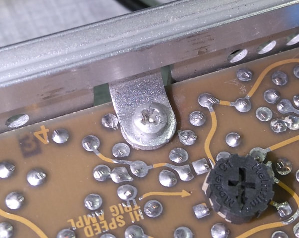
An item of concern: The four metal flaps are so close to the traces of the A1 main board that a short circuit is very likely. I decided to insert a spacer between the board and the 4 flaps to mitigate this.
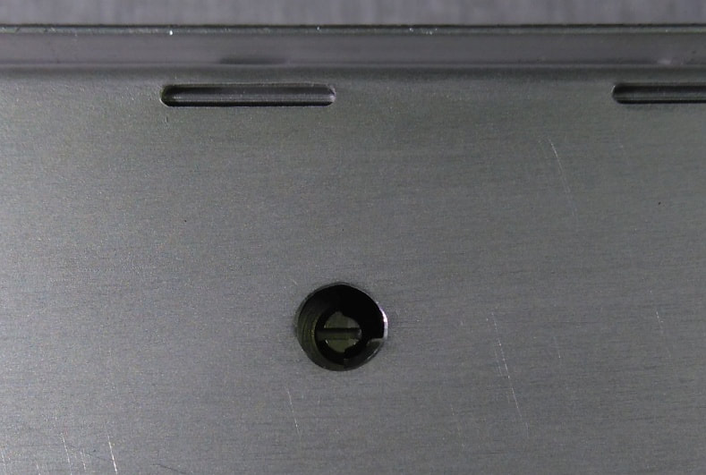
A hole was made in the side shield to access the trimmer C102, even when the TG 501 is inserted in the TM 500 mainframe.
|
TG 501 Time Mark Generator
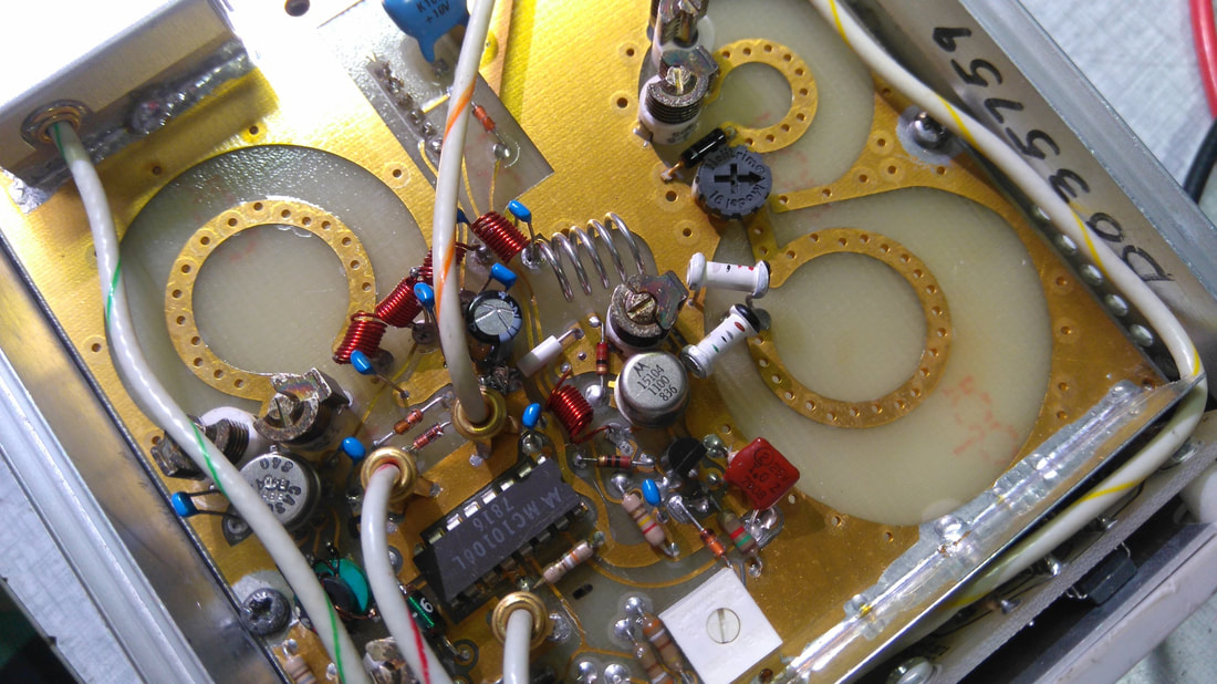
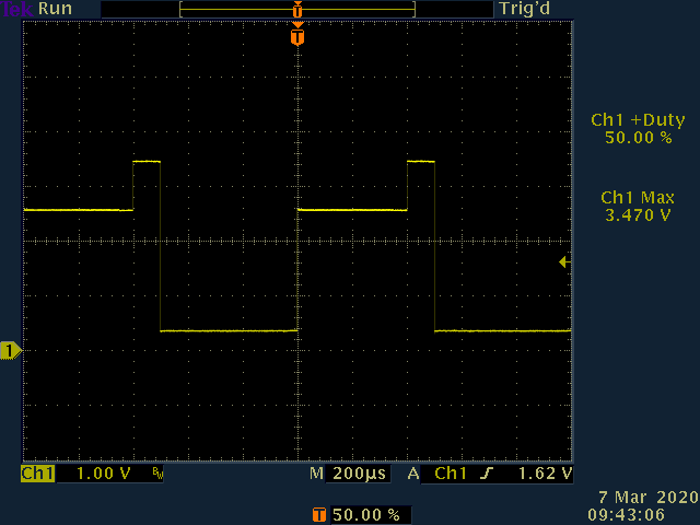
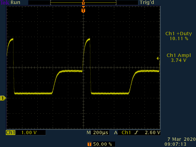
This module, made for the TM 500 series of power main frames, is handy for adjustment and debugging of oscilloscopes. It is also one of the items on the list of required instruments in the service manual of the popular series 2400 oscilloscopes from Tektronix. In connection with a calibration of my 2465B I found a TG 501 at a modest price and in a decent physical shape with the fragile plastic subpanel intact, but in an unknown functional state. This often spells "repair", and this time it was no different. To summarize, and perhaps for your inspiration, this is what I found: 1) The 1 MHz crystal had fallen out of its socket and was rattling around when I received the TG 501. The crystal was put back in place, and the TG 501 would then output a signal, though not very stable. 2) The TG 501 actually died while I was fiddling with the knobs. It turned out that C495 (a 100 µF / 20 V tantalum capacitor) had now become a short. It was replaced with a Rubycon 100 µF / 25 V type ZLG. A similar capacitor, the C615, was replaced also, just as a precaution. 3) The frequency offset display showed values that were wrapping around as I varied the frequency. The reason was simply that the 1 MHz variable clock was way too off, and adjusting trimmer R145 for a proper center frequency did the job. 4) One of the fast/slow LEDs was permanently lit when operating the TG 501 in variable frequency mode. By inspecting the signals of the phase comparator which controls the LEDs I found that the U150 (a 7473) was not working correctly, and was replaced with a 74HC73E. 5) After power-on the output frequency was much too high, and only after fiddling with the variable frequency a while the frequency would jump down into place. Among other things I suspected leakage current through integrator capacitors C250 and C251, which I replaced with a 22 µF ceramic capacitor, but it had no effect. It turned out that U230 (another 7374) was not operating properly. The way it worked made the 100 MHz PLL find a false lock. The 7374 was replaced with a 74HC73E, and the PLL then worked as intended. 6) The center conductor of 2 out of 3 coaxial cables going into the BNC front panel connectors was bent. There was no indication of previous repairs, so perhaps the TG 501 had left the factory in this condition. 7) Finally, the light bulb was replaced with an orange LED, and R629 was changed from 10 Ohm to 200 Ohm. I would not like to go through the annoying dismantling of the TG 501 again just to replace the bulb when it eventually fails. Once I had completed the repair of the TG 501 I adjusted trimmer capacitor C102 for a frequency error below 0.5 ppm. I had made a hole above the trimmer in the side shield so that I could trim the frequency after having assembled the TG 501. If the TG501 is located in the rightmost position of the TM mainframe one may access the trimmer through one of the punched ventilation holes in the right side. The frequency will drift once the TG 501 has heated up, so trimming has to be done under real conditions when inserted in a mainframe. Use a proper, non-conducting trimming tool, or a flat-blade screwdriver with an insulating sleeve made of heat shrink tubing, for the adjustment. If the frequency accuracy is not good enough then take a look at its schematics to find out how to use an external frequency reference. The TG 501 is prepared for an external reference, though some (documented) changes are required. I will refrain from this as the accuracy is OK for the intended purpose of oscilloscope calibration. |
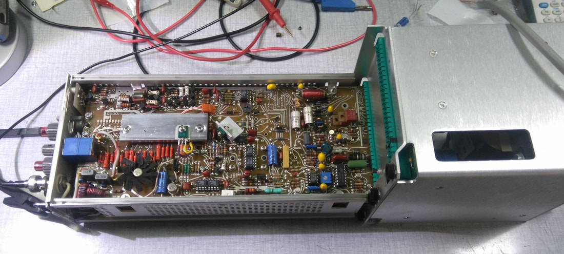
My PG 506 undergoing repair and modifications (of which the heat sink for Q280 is easy to spot), connected to a TM502A mainframe witgout casing.
A partially weak drive by the defective U620 (upper picture) prevents the output transistor of the photocoupler U255 to turn off completely (lower picture), thereby having a too weak a drive for the transistors Q320 and Q270 to pull down the output voltage.
The U620 was replaced with a 74HC73E. |
PG 506 Calibration Generator
The PG 506 is made for the calibration of oscilloscopes, and provides a square wave from 0.2 mV to 100 V amplitude in a 1-2-5 sequence, with a fixed 1 kHz frequency. It also provides a fixed amplitude square wave with selectable frequency, and a pair of fast-rise outputs, suited for oscilloscopes up to about 500 MHz bandwidth. All this is combined in a handy module for a TM 500 series mainframe. So why am I not a huge fan of the PG 506? In short, the design is awfully convoluted, or dare I say, it is an awful design. There is a lot of cam-activated switches that route signals, there are relays that change power supply mode, and too much can go wrong with all this switching around. There are too many parts of the design that depend on other parts, making debugging a hassle. However, when my PG 506 failed, and I still wanted to use it for calibrating my 2465B, I had to bite the bullet and repair the PG 506. With some effort the PG 506 can be wired for an external supply so that debugging can take place outside the mainframe. I found, however, that it was by far the easiest and quickest to remove the casing of my TM502A mainframe, as shown on the picture to the left. Even then, the access to large parts of the boards remains very limited, and the boards have to be mounted together for the PG 506 to operate. In summary, this is what I found and did: 1) There's a lot of low-quality sockets in the PG 506, and evidence of bad connections were observed. I replaced a few sockets with quality models. 2) The falling edge of the output pulse was way too slow, and would not go all the way down but seemed to be stuck, but would eventually go down before the end of the cycle. It turned out to be a defective U610 (a 7473) which I then replaced with a 74HC73E. The U610 could not drive the optocoupler U255 properly, which then prevented Q320 to pull down when needed. The 7473 is the exact same IC that was defective in the TG 501 above, so perhaps there was a production issue with these. 3) There were intermittent errors when operating the switches, and a good cleaning was called for. Things improved, but still, the amplitude was not stable, especially when switching from 10 V to 20 V, as explained below: 4) The voltage for the 20, 50 and 100 V ranges was unstable, and too low. To be more precise, the voltage seemed OK right after the moment I would switch from 10 V to 20 V, but the voltage would within a second go down to about 75 %. What happended was this chain of events: First of all, the current through Q190 in the voltage reference loop was larger in the 20, 50 and 100 V ranges than in the other ranges. This resulted in a reduction of the collector-emitter voltage of Q190 approaching zero due to the voltage drop over R190, and this inevitably resulted in a reduction of the reference voltage, and then of the 100 V rail, which is used as the power source for the reference loop. The process would stabilize at about 75 V. So, in this error case, the reference became dependent on a voltage derived from the reference. A simple fix was to decrease the value of R190 by adding a 10 kOhm resistor in parallel. Q190 was replaced with a BF471 in a TO-126 casing due to the increased power dissipation. 5) The transistor Q280 runs hot, and it was replaced with a BF472 in TO-126 case mounted on a heatsink (see the picture). There's a spare threaded hole ready for Q525. Q290 also gets hot, but has a lower dissipation than Q280. I replaced Q290 with a BF472, and added a small heatsink. So now, I can get back to the calibration of the 2465B ... ! |
