Thermometry
Temperature, its measurement and its control are essential to the development, characterization and servicing of electronics. On this page I show a few items in the lab that are related to temperature.
Temperature, its measurement and its control are essential to the development, characterization and servicing of electronics. On this page I show a few items in the lab that are related to temperature.
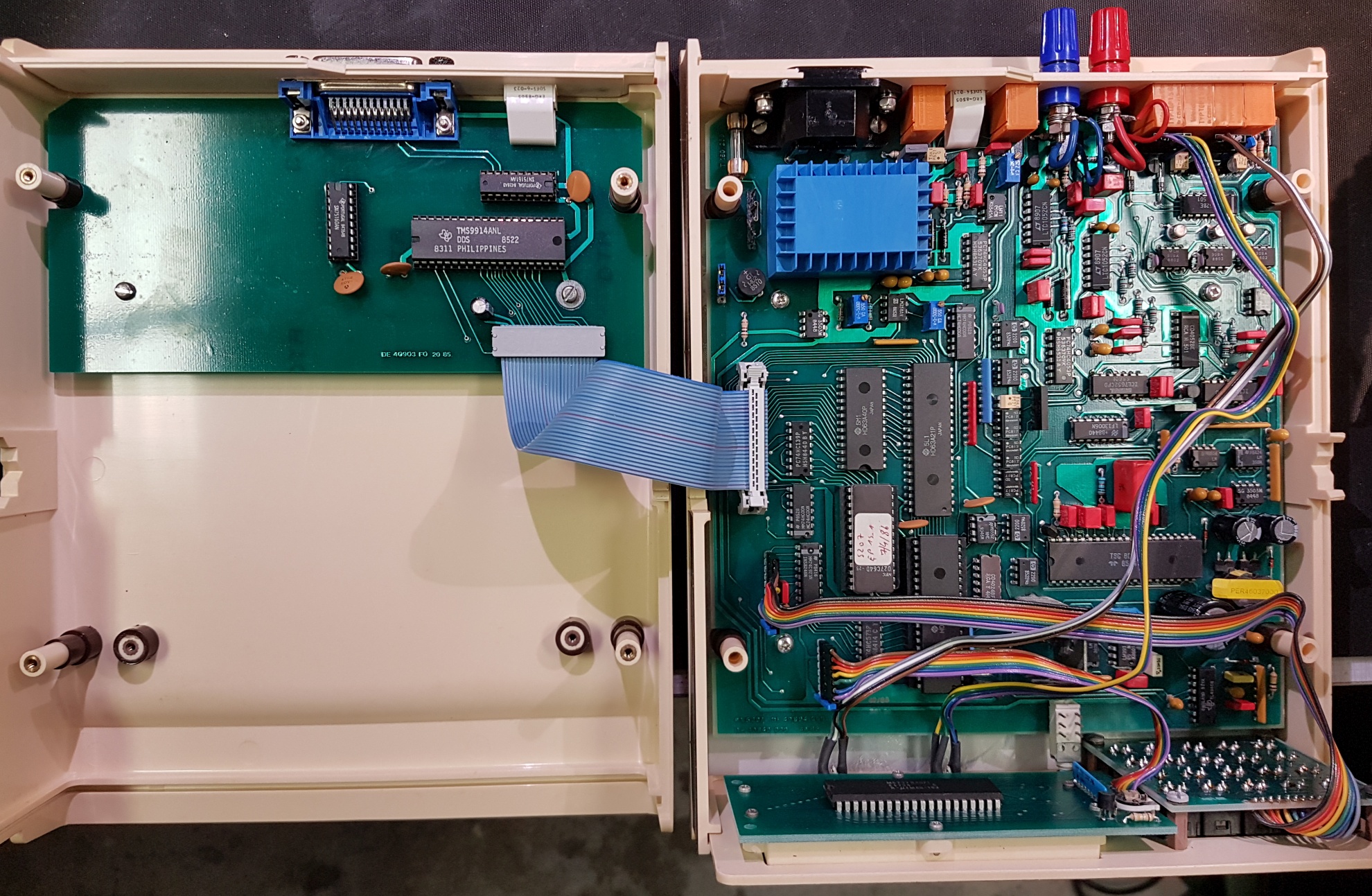
Inside view of the PN 5207. The red/blue terminals and the GPIB connector on the back are not the original.
|
AOIP PN 5207
A rather old thermometer, cased in a cheesy plastic enclosure, but still useful for temperature measurements in the lab. It features GPIB for logging, and two measurement channels, which is a nice feature for simultaneous measurement of ambient and internal temperature. The best resolution is 10 mK, and best accuracy 20 mK, which is acceptable for general lab work, but perhaps not really sufficient for labelling the PN 5207 a "high precision calibrator thermometer". The term "calibrator thermometer" was used by AOIP to highlight the model's sensor simulator feature. The PN 5207 I got had apparently been stored at a humid location for too long time. The sensor connectors, the GPIB connector and the sensor output terminals were all corroded and had to be replaced. Luckily, the parts inside the enclosure seemed OK, though I had to give the ICs in sockets some massage to make the thermometer work. The connectors on the front panel were identified as Binder 09 0316 80 05, to be used with Binder 09 0313 00 05 plugs. I could not identify the GPIB connector, so it was replaced with a model CIB24SRA from L-com. The terminals on the back were replaced with common banana plug screw terminals. When got the PN 5207 the LCD-display was difficult to read, with a lot of missing or vague segments. The solution was to dismantle the display assembly and to clean the contact pads on the circuit board and the conductive rubber profile. I had to clean the contact surfaces again about a year later, so I would not be surprised if bad displays are a common issue with the PN 5207. |
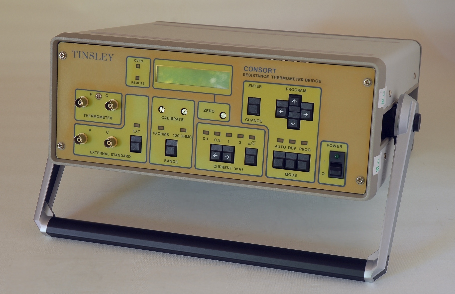
The Tinsley Consort 5840E
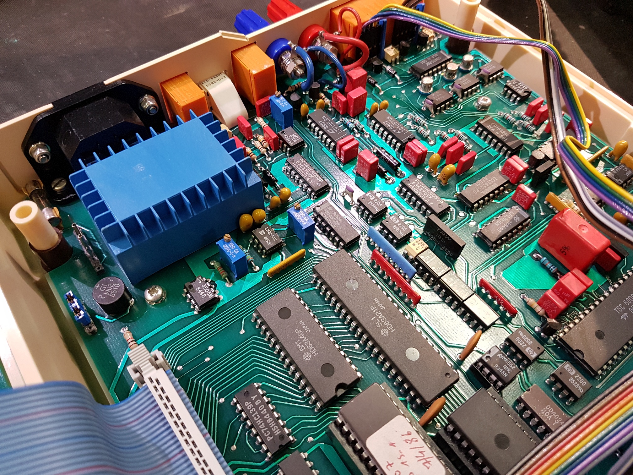
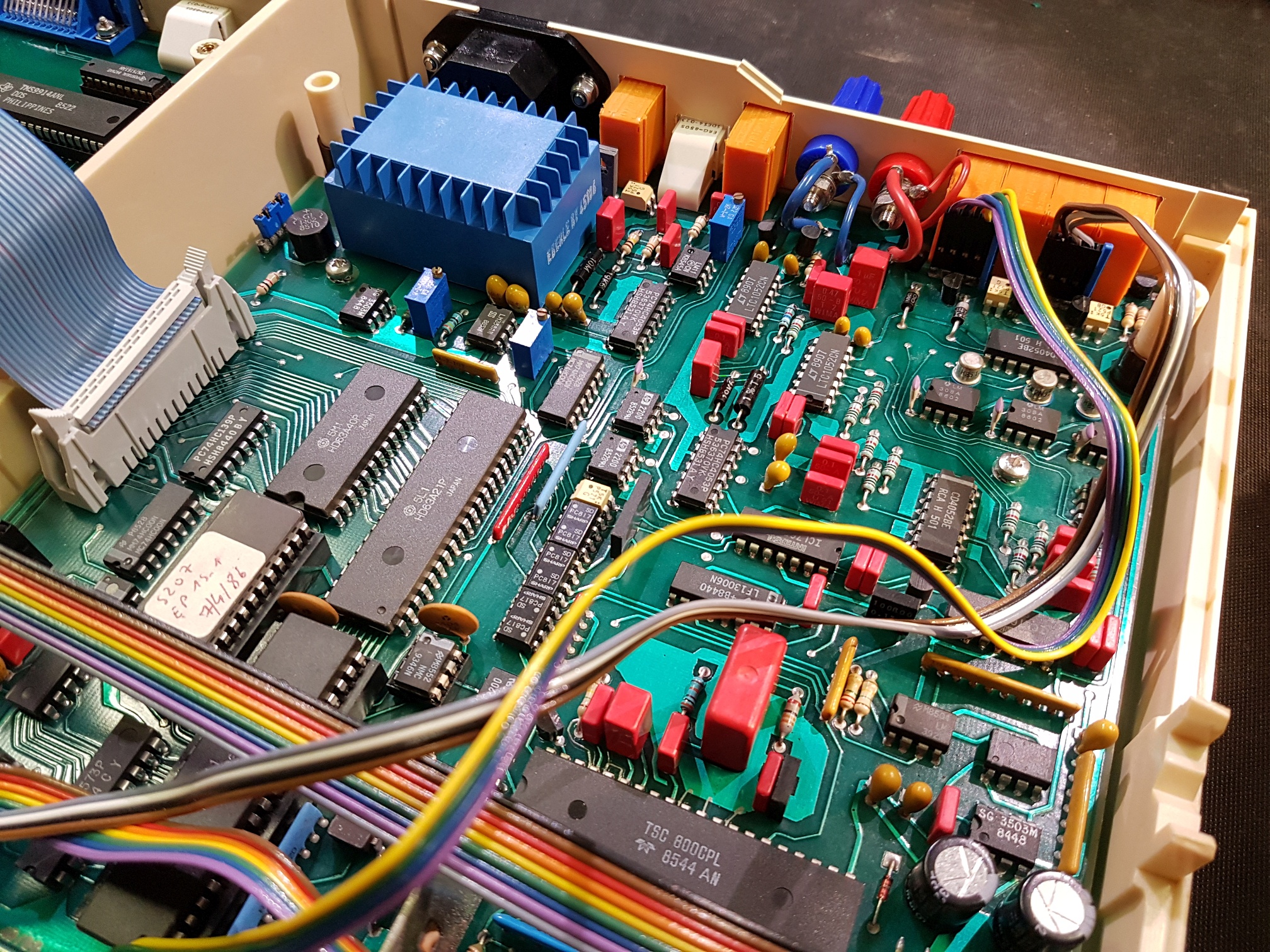
A look inside (to be uploaded)
I have made a scan of the Operating Instructions for the Tinsley Consort Type 5840E. Note that the document contains two pages 27 with different wiring for RS-232.
|
Tinsley Consort Thermometer Bridge Type 5840E
This is an AC bridge based on an inductive voltage divider, designed to measure 4-terminal resistance thermometers, either platinum thermometers in the range RO 2.5 Ohm through 100 Ohms, or Rhodium Iron thermometers with RO 40 or 100 Ohms. The bridge has two ranges: 10 Ohm for measurements in the range 0-15.99999 Ohms, or 100 Ohms for measurements in the range 0-350.0000 Ohms, using the internal ovenized resistors for comparison. For "normal" measurements with a 25 Ohm or 100 Ohm platinum resistance thermometer only the 100 Ohm range is used. The instrument allows the user to enter thermometer parameters so that the resistance may be converted into temperature. With an appropriate platinum resistance probe Tinsley claims that it's possible to reach a measurement uncertainty of about 6 mK. For sure better bridges are available, but the 5840E still boost my temperature measurement capabilities with an order of magnitude compared to the AOIP PN 5207 shown above. The instrument may also measure the ratio between two external resistors, which allows you to compare resistors within certain limits: In the 10 Ohm range the ratio is 0-1.599999, and in the 100 Ohm range the ratio is 0-3.500000. This is useful for matching resistors, or to select resistors for building a resistive voltage divider. Mind you, however, that the bridge is an AC bridge, and uses a measurement frequency of 75 Hz at 50 Hz mains, and 90 Hz at 60 Hz mains. At the impedance levels targeted by the 5840E the parasitics at these frequencies should have little impact, but the high resolution of the 5840E requires that the effects are estimated. |
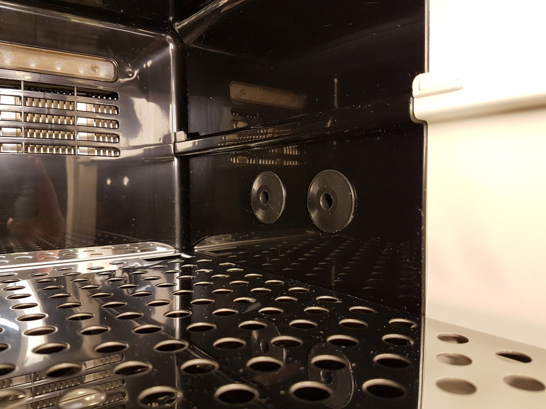
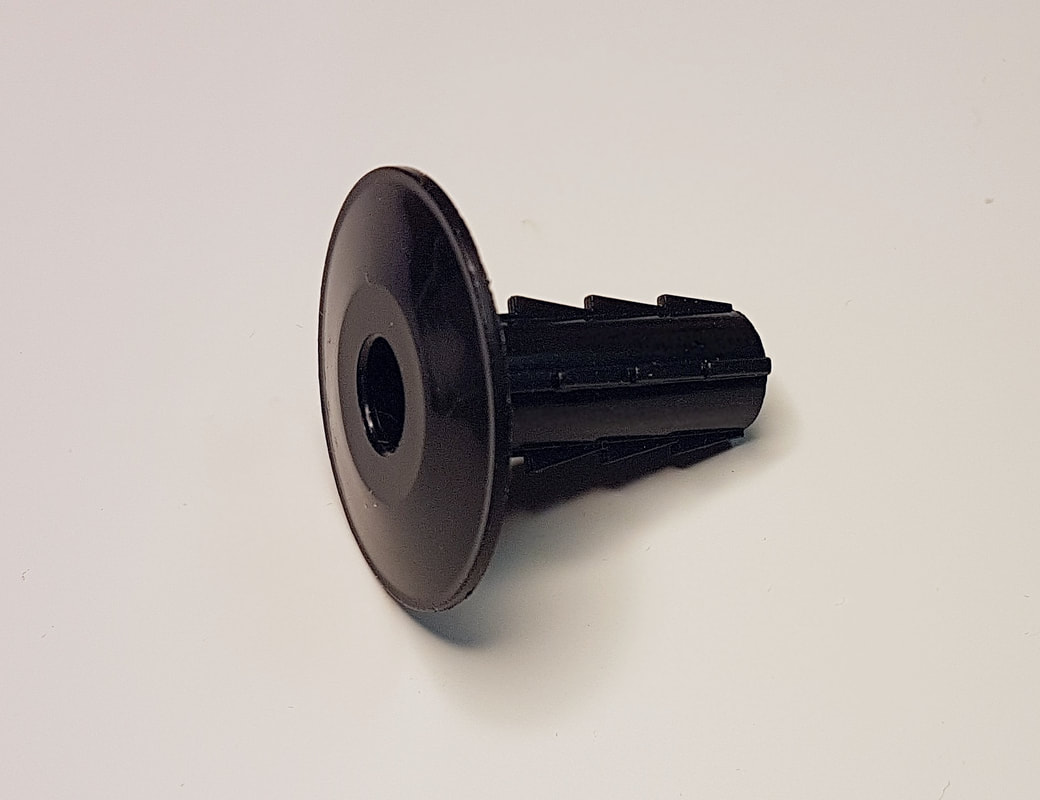
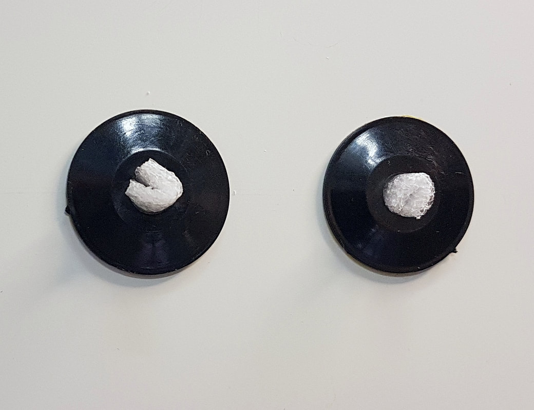
Service ports added to the VWR incubator. The feed through wall covers protect the insulation foam. The covers used here require a 10 mm hole, and have an internal diameter of about 7.6 mm. One cover is used from each side of the incubator's wall. The covers are cut to length and glued in place. A foam plug is used to cover the hole.
|
VWR 0.65CF / Thermo Scientific IMC 18
Temperature test chambers or metrology air baths are valuable assets, which must be the reason why so many are insanely expensive. Used chambers at a reasonable price are very hard to come by, so if you are looking for a "poor man's temperature chamber", something like the VWR model 0.65CF, aka. "Personal Low Temperature Incubator", may be worth considering. A similar model IMC 18 is available from Thermo Scientific, and both are made by Thermo Electron LED GmbH. The incubators were made for keeping biological or chemical samples at a constant temperature, but with some consideration they could be used for testing electronics. The temperature range is limited to 17 C to 40 C, but this still allows you to carry out a range of tests. Do not expect stellar temperature stability or accuracy, but you likely want to have temperature logging anyway. The cooling power is low, so testing has to be limited to passive components or to designs that consume only little power. The temperature change per time interval is also low, but again, if we are looking for finding temperature coefficients of devices, for example, this is quite OK. A major advantage of these chambers is that they are Peltier based, and emit only little acoustic noise. The weight is much lower than "real" test chambers, and they can be located on a test bench close to other instruments. The incubators do not have any service ports for cabling, but a service port is easily made: I drilled a couple of 10 mm holes on both sides and glued a feed through wall cover on each side. This cover has room for PT100 sensors, for an RG-58 cable, or for a cable with an SMB connector, but it will not allow a BNC connector through. |
|
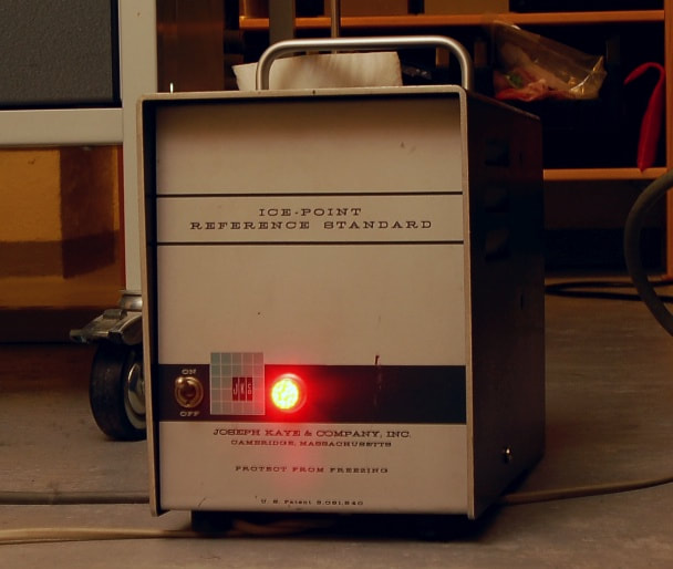
Kaye Ice-Point Reference Standard
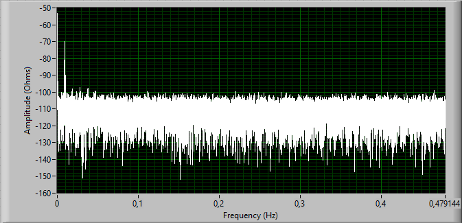
This is a very useful device which provides an ice-point temperature by maintaining an equilibrium of ice and water within a reference cell by means of an expandable bellows connected to a microswitch, which then switches a Peltier cooler on and off. The standard has 4 wells for immersion of sensors. The stability is within 25 mK, and typically 10 mK. The accuracy is typically 20 mK, and better than 50 mK, and Kaye claims that there's no long term drift, all guaranteed by the design with the sealed equilibrium cell. The model shown in the picture is an older model, but the model K140 sold today looks very similar, as Kaye appears to have changed only the artwork and the power-on lamp. This must be a product with one of the longest track records on the market. The ice-point reference not only serves as a calibrator for thermal sensors, it also serves as ice-point reference for thermocouple reference junctions. The unit I found at a garage sale only had to be cleaned, and the fan replaced, and then it was as good as new. The switching of the Peltier cooler has the effect that there's a slight oscillation of the temperature. This is demonstrated on the graph which shows an FFT of the measured resistance over 24 hours of a Pt100 sensor immersed in one of the wells. The amplitude was close to 3 mΩpp, corresponding to some 8 mKpp, and the frequency peak of the oscillation was about 9.3 mHz. The y-axis shows the impedance in dB relative to 1 Ω. |
|
(Picture to be added)
|
Ametek / Jofra Temperature Calibrator 650SE
A dry block calibrator comes handy for checking and calibrating sensors, provided the dry block calibrator itself is kept under calibration. The model 650SE has a working temperature range between 50 °C and 650 °C. With a specified accuracy of ±0.6 °C and a specified stability of ±0.05 °C the 650SE is no top performer, but serves well for industrial applications. In comparison, Ametek claims an accuracy of ±0.04 °C and a stability within ±0.005 °C for their RTC series. The accuracy and stability of any dry block calibrator do not matter, however, if you do not use the right insert with an internal diameter that matches the probe, and made of the metal as specified for the calibrator. The right insert ensures a proper thermal connection between the well and your probe, and it will not melt or get stuck, I might add. |
|
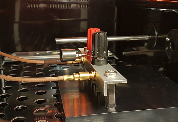
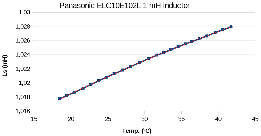
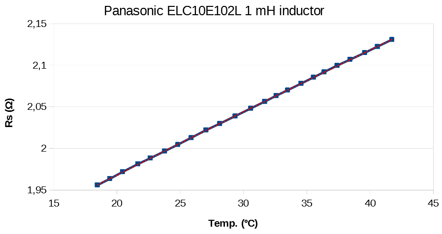
Characterizing components over a temperature range
Quite often one would like to know how a component changes with temperature, but to one's dissapointment the data sheet remains silent on the topic. As an example, inductors that you consider for an LCR-filter may or may not have too much drift over temperature, but the temperature coefficient of inductors is typically not specified. However, if you know how the inductor behaves over your target temperature range you can set up a Monte Carlo analysis of the filter that will reliably tell you what to expect. The figures on the left show an example of a Panasonic 1 mH shielded ferrite inductor's Ls and Rs values, measured by a Quadtech 7400 at 1 kHz, and at different temperatures. The inductor was placed in the VWR incubator while monitoring the temperature with a Pt100 sensor and the AOIP PN 5207. The average temperature and component values were found over at least 1 hours of measurements after the temperature had settled. The red dotted lines represent a second order fit to the measured data. The linear parameter of the fit is dominant, and it's found that Ls changes with some +606 ppm/K, while Rs changes with some +0.402 %/K, which is close to the temperature coefficient of copper (+0.394 %/K at 20 °C according to J. H. Dellinger, The Temperature Coefficient of Resistance of Copper, Bulletin by the Bureau of Standards, Vol.7., No. 1, 1910.) Though the temperature coefficient of the series inductance Ls seems quite high, it may be OK for a properly designed lowpass filter: What's interesting is how the transfer function inside the passband behaves, and that the stopband attenuation is sufficiently high, in spite of component variations. |
