Data Precision 8200
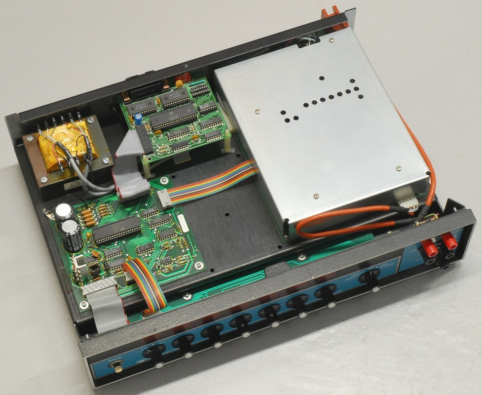
Above: The 8200 with a home made metal shield installed.
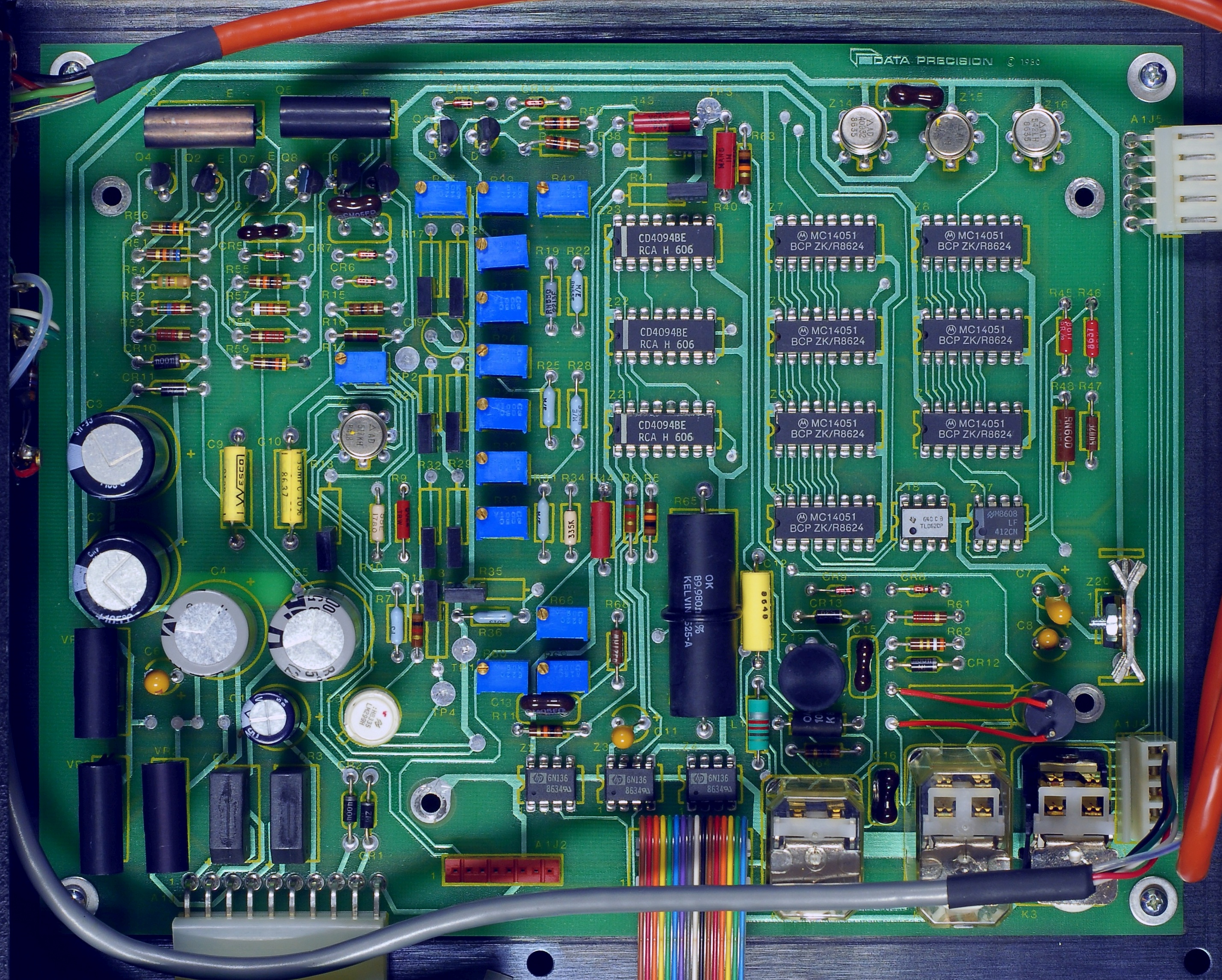
Above: The 20-bit DAC-board, with the shielding cover removed. The picture was taken before modifications. The board includes the analog power supply. Click on the picture for a larger view.
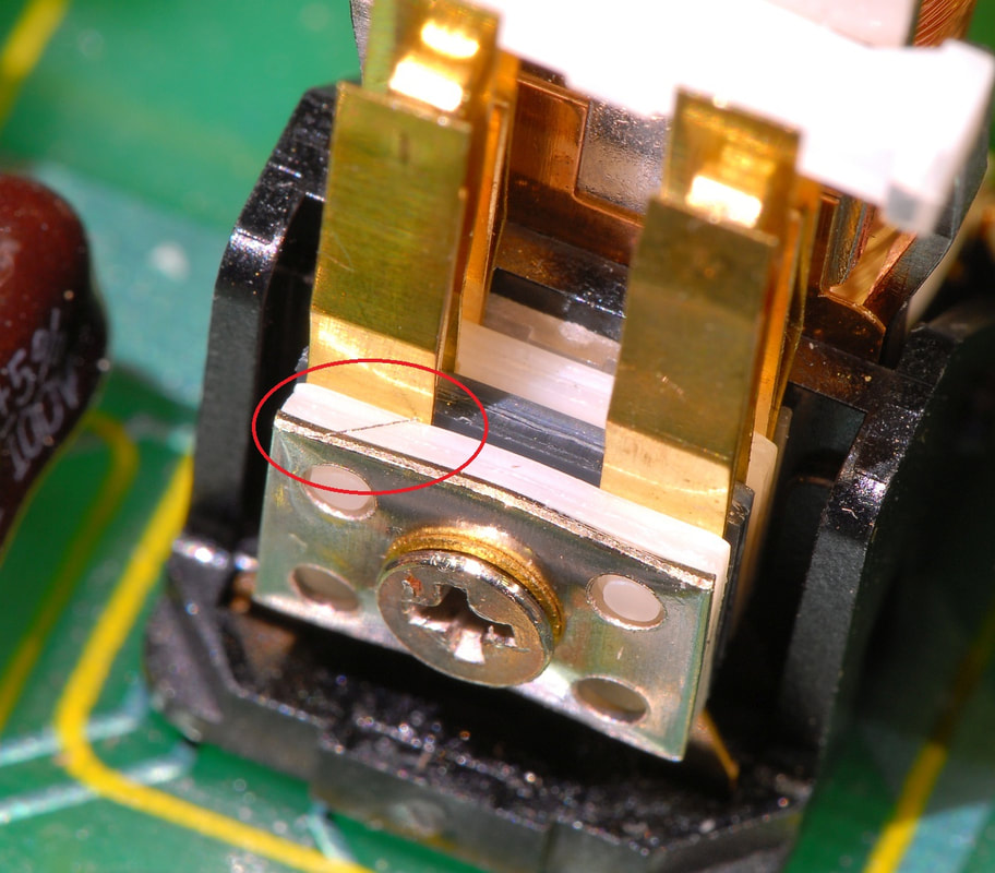
By consulting the schematics and measuring voltages around the 8200 it became increasingly likely that a short between the guard node and the output of the 100 V stage was located close to the relay K2. I was both surprised and pleased to find this little fella...
|
The 8200 is often seen on the market for used test equipment, but the asking prices are usually way too high. Also, the units often have strong signs of use. With a great deal of patience I found a unit in fine condition and with the GPIB option included, though the 100 V range was reported to be defective. A photo posted by the seller showed that the metal shield for the analog board was missing, which strongly indicated that someone had tried to repair the 8200 at some point in the past. However, the tidy inside of the unit convinced me that the 8200 likely could be fixed...
When I received the 8200 it did not produce any meaningful output in its 100 V range, as expected, but otherwise it seemed to behave correctly. Even the rotary decade switches, which seem to have bothered some 8200 owners, worked flawlessly. An investigation showed that the 100 V amplifier stage went into current limitation, and the reason was that the output of the 100 V amplifier was connected somehow to the guard. When the jumper strap between the guard terminal and the LO terminal was removed, the 8200 would work properly in the 100 V range. It took a couple of hours poking around the 8200 with a multimeter before I found the culprit: A tiny piece of metal left inside the K2 relay made an unwanted connection between the output of the 100 V amplifier and the frame of the relay, and thereby the threaded stud which is connected to the guard node that runs below the relay. |
|
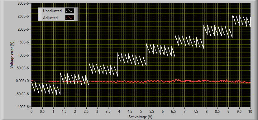
The D/A-converter of the 8200 requires some caring to provide the level of linearity one should expect from a calibrator with this resolution. The graph on the left shows the voltage error of my 8200 in the unadjusted condition (white) and in red, after being adjusted. In the unadjusted condition selected op-amps and the voltage reference had been replaced, but no adjustments of the octade divider and the weighting network had been carried out.
The graph was made by changing the set voltage through the IEEE interface from 0 to 10 V in 1 mV steps and measuring the voltage by an Hewlett Packard 3458A multimeter. You can clearly see the discontinuities that relate to the misalignments of the :8 and :64 stages. Some steps are larger than the resolution (ie. the differential non-linearity may be larger than 1 LSB), so a monotonic behaviour of the 8200 in this condition should not be expected. Before you take a stab at any adjustment, be sure to study the manual, and not the least, the very fine work by Hartmut Henkel in his "Repair of Data Precision Model 8200 6½-Digit Voltage & Current Calibrator" which you may find at http://www.hhenkel.de/data-precision-8200/repair-8200.html, and with a .pdf available at http://www.hhenkel.de/data-precision-8200/repair-8200_p.pdf. In this document you find an in-depth coverage of the theory behind the D/A-converter, and some fine hints on how to carry out the calibration, such as a proper order of the adjustment of the trimmers. In my 8200, I had to shunt R43 with an 82 MΩ resistor in order to be able to trim the carry of the :64 stage successfully. Also, I found that resistor R44, for which there's no trimmer, actually had to be made slightly lower by shunting it with a 2 GΩ resistor in order to improve the carry function for the 4 lower sections. The :8 stage is without doubt the most sensitive one, and the carry function is clearly temperature sensitive. Without the inner metal shield, the carry shifts the order of an LSB. This is sort of OK, as the the metal shield is supposed to be in place when carrying out the calibrations. The bad thing, however, is that putting the black top cover in place also shifts the :8 carry, and about half an LSB. You can adjust every carry as much as you like, but merely putting the top cover in place will to some extent mess up the good work. It could be an idea to replace resistors R38 and R41 with top class hermetic metal foil resistors to have a more robust carry function of the :8 stage. |
