True Time 60-TF modification
My True Time 60-TF WWVB frequency comparator has been heavily modified to address a couple of safety issues and to squeeze out some better performance. When I first got the 60-TF an inspection of the inside revealed the following:
The safety issues are serious, and if you're an owner of one of these oldtimers I strongly recommend that you take a closer look inside and determine if these issues apply to your unit.
As I live in Denmark where the mains voltage is 230 VAC I simply replaced the transformer with a solid toroid transformer for 230 VAC. The transformer is rated at 2x17.5V/1A + 7.35V/1.8A and includes a static shield. A new base plate supports the transformer and provides stiffness to the chassis. I reduced the size of the power board and got rid of the edge connector, and the board is now firmly mounted on an L-profile that supports the transformer base plate. I replaced the original IEC power inlet with a model with integrated EMI filtering to get rid of the mains filter on the power supply PCB. The fuse holder was replaced with a model with 250 VAC rating. The ground pole of the IEC inlet and the static shield of the transformer got firmly connected to the chassis. As a bonus the power inlet and the fuse holder now have the necessary approvals (UL, Demko, etc.)
The heat sink arrangement in the original design is inadequate and allows the 5V regulator to heat up and add to the temperature rise inside the chassis. I improved the cooling of the 5V regulator by adding an aluminium bar to transfer the heat to a heat sink located on the outside of the chassis. This reduced the temperature rise from about 35 °C to 12 °C, measured on the metal surface 5 mm from the regulator.
The rectifier diodes for the 5V rail are now SR340 3A Schottky-barrier types that ensure a low operating temperature. I replaced the electrolytic capacitors with models with improved reliability: For the 5V rail the capacitor is now rated at 4700 μF/35V 105°C, and the capacitors for the +15V and -15V rails are 220 μF/63V 105°C types.
In addition to the power supply issues, the receiver suffers from a number of design flaws that challenge the performance, at least in the version I got:
As the MSF carrier goes down to zero the receiver PLL will produce slight frequency bumps with 1 Hz rate, even now that the offset in the phase detector has been reduced. By reducing the loop bandwidth, you'll get less variation, but before just ironing out the variations through an even slower loop, I decided to add some circuitry to address the issue. First, the output of the loop amplifier got filtered by a 1 Hz notch T-filter. This could be done without stability issues as the loop bandwidth had already been reduced. Secondly, a blanking circuit controlled by the extracted time code was added so that the output of the phase detector is kept about the average while the input signal is low. A simple pulse stretcher circuit extends the time code pulse to maintain blanking until the phase settles. When the only filtering at 60 kHz is the original LC filters located on the input module I found that the pulse should be stretched with about 10 ms. This has to be increased in case a crystal filter is inserted in front of the receiver PLL.
In order to enhance the functionality of the 60-TF I made a few other amendments to the design:
The paper chart recorder was replaced with a moving-coil meter, and a 4-pole switch mounted on the front panel allows me to monitor either the frequency detector voltage from the acquisition help circuitry (see below), the phase detector voltage, the VCXO voltage or the comparator voltage. A simple emitter follower buffer was added to the time code output of the receiver board to increase the drive strength and to relieve the input module from the current changes. The buffer now drives a yellow LED on the front panel, the time code output on the back panel, and the blanking circuitry (via the pulse stretcher) added to the PLL receiver board.
- The rectifier diodes for the +5V rail run way too hot. As a result, there's a telltale discoloration of the power supply PCB just below these diodes. My 60-TF consumes about 0.9 A on its +5V rail, and it would be prudent to replace the 1N4005 diodes with devices that have 2 A or 3 A rating.
- The transformer runs too hot, and parts of it have been slightly discolored. I would think the winding for the +5V rail needs a higher current rating (no figures are printed on the transformer). In comparison, the -15 V and the +15 V rails consume about 30 mA and 60 mA respectively.
- There are thin wires crossing the heat sink, and the combination of thin insulation, a hot heat sink and power is not appealing. Also, the wires for the mains voltage are wrapped tightly together with the low-voltage wires.
- Finally, the weight of the transformer bends down the power supply PCB so that the solder pads almost touch the chassis. This definitely has to be fixed before putting the unit into service.
The safety issues are serious, and if you're an owner of one of these oldtimers I strongly recommend that you take a closer look inside and determine if these issues apply to your unit.
As I live in Denmark where the mains voltage is 230 VAC I simply replaced the transformer with a solid toroid transformer for 230 VAC. The transformer is rated at 2x17.5V/1A + 7.35V/1.8A and includes a static shield. A new base plate supports the transformer and provides stiffness to the chassis. I reduced the size of the power board and got rid of the edge connector, and the board is now firmly mounted on an L-profile that supports the transformer base plate. I replaced the original IEC power inlet with a model with integrated EMI filtering to get rid of the mains filter on the power supply PCB. The fuse holder was replaced with a model with 250 VAC rating. The ground pole of the IEC inlet and the static shield of the transformer got firmly connected to the chassis. As a bonus the power inlet and the fuse holder now have the necessary approvals (UL, Demko, etc.)
The heat sink arrangement in the original design is inadequate and allows the 5V regulator to heat up and add to the temperature rise inside the chassis. I improved the cooling of the 5V regulator by adding an aluminium bar to transfer the heat to a heat sink located on the outside of the chassis. This reduced the temperature rise from about 35 °C to 12 °C, measured on the metal surface 5 mm from the regulator.
The rectifier diodes for the 5V rail are now SR340 3A Schottky-barrier types that ensure a low operating temperature. I replaced the electrolytic capacitors with models with improved reliability: For the 5V rail the capacitor is now rated at 4700 μF/35V 105°C, and the capacitors for the +15V and -15V rails are 220 μF/63V 105°C types.
In addition to the power supply issues, the receiver suffers from a number of design flaws that challenge the performance, at least in the version I got:
- The 60 kHz filter/receiver board has been positioned in such a manner so that the input of the board is close to the BNC output, and the output of the board is close to the BNC antenna input, with some long coax cables going forth and back. It seems this is done to allow the user to get access to the gain setting trimmer through the back panel. I flipped the board 180 degrees to get a better cabling and less unwanted coupling to the sensitive input.
- The bandwidth of the receiver PLL is too wide. This allows the PLL to pull in to the carrier quickly (less than 30 s), but phase variations of the 60 kHz carrier propagate merrily to the 1 MHz output signal. No need to point out that this efficiently ruins the Allan deviation over a wide range of time intervals. I redesigned the PLL so that the bandwidth got reduced with a factor of about 60. As the pull-in time is approximately proportional to the power of three of the inverse of the loop bandwidth, the pull-in time was increased dramatically. Through careful adjustment of the crystal oscillator I managed to keep the pull-in time within acceptable limts, but in order to prevent aging or other changes from becoming an issue I later added an acquisition help circuitry (see below).
- The TTL devices are poorly decoupled which results in various switching spikes being spread around in the design. Decoupling was added directly over the TTL devices where it seemed to be in place.
- The coax cable for the 1 MHz output is series terminated with a 270 Ω resistor. This results in substantial ringing at the end of a cable when not terminated in 50 Ω, and this may cause false triggering of a frequency counter. I have added a 62 Ω resistor to GND close to the 270 Ω series termination to obtain a source impedance close to 50 Ω, and as a result, I do not necessarily have to terminate the 1 MHz output in 50 Ω.
- The gain in the phase detector is so large that it clips, thereby preventing linear operation for all phase angles. The gain was reduced as a part of the reduction of the PLL bandwidth.
- There's a very high offset from the phase detector at low signal levels. This is a direct consequence of how the ports of the MC1496L Gilbert-cell mixer are used in the 60-TF. For the MSF service where the carrier is turned completely off as a part of the modulation scheme, the result is a repetitive pattern of substantial phase jumps and a poor Allan deviation. At low input levels the 60-TF will even loose lock and will drift off rapidly to the frequency limit of the oscillator. With the original loop bandwidth the loop will obtain lock quickly once the signal returns, but the prospects of regaining lock will become more dim when reducing the loop bandwidth. In all, there were impelling reasons to reduce the phase detector's offset. I swapped the use of the ports of the MC1496L to be able to curb the offset. Check out the schematics below. Also, the bias offset current of the 741 op-amps in the original design may get so large that it may compromise the function of the PLL. I replaced the 741's with op-amps far better for the job: The OP177G for the phase detector, and the AD711KN for the loop amplifier (other devices may serve the purpose equally well, but these two were readily available in my lab).
- The 60 kHz carrier from the divider chain on the PLL receiver runs close at the edge of the board, and this will unavoidably increase the coupling to the sensitive receiver. At low input levels the original 60-TF has an issue with self-induced pollution of the input signal, and an unshielded wire carrying 60 kHz TTL is not what you need. As the 60 kHz drive signal for the MC1496L in the original design is much higher than needed, I simply reduced the level with an L-pad and replaced the PCB line with a coax cable close to the edge connector of the PLL receiver board. This was an improvement, but there was still some coupling from the 60 kHz TTL on the receiver PLL to the receiver board, which produced a slight phase offset at low input levels. This was removed by adding shielding with proper grounding around the dividers that produce the 60 kHz TTL signal, and by adding solid decoupling in combination with an inductor in series with the 5V supply to prevent the AC component in the wire between the power supply and the PLL board to couple to the receiver input.
- The "LOCAL STD" PLL (the left board on the picture) includes a 20 kHz TTL signal which has a 3rd harmonic that gets coupled into the 60 kHz amplifier board; Depending on the phase of the "LOCAL STD" there will be an offset in the receiver PLL's phase detector. The phase comparator also produces a 20 kHz TTL pair with varying duty cycle that corresponds to the phase between the "LOCAL STD" and the receiver PLL, and this pair runs (unfiltered) in two wires to the receiver PLL. The result of the signal pollution is phase excursions and frequency drift for low signal levels on the antenna input. The coupling of the signals from the "LOCAL STD" PLL board has been reduced by filtering the phase difference pair locally on the "LOCAL STD" PLL board, by adding shielding with proper grounding around components that handle 20 kHz and 60 kHz TTL signals, and by adding solid decoupling in combination with an inductor in series with the 5V supply.
- The negative reference voltage for the varactor diode is taken directly from the negative rail. Any rail noise or voltage variations will propagate into the PLL. The voltage for the varactor has been decoupled with a fairly large time constant to allow the PLL to track any voltage changes.
- The time code data extraction of the 60 kHz input module operates with a very long time constant in its level determination low-pass filter plus a too high decision threshold. This gives way too many errors in the time code. Changes were made to the low-pass filter, the threshold and the rectifier to improve data resilience over a wider range of input levels.
- The final stage in the chain of amplifiers suffers from slew-rate limitation. The slow 741-type op-amps were replaced with AD711KN where needed. Rail decoupling was also improved to prevent oscillation at high gain settings.
- Due to an antenna input feed resistance of 3.3 kΩ and a 150 Ω series resistor in the positive rail for the input module the antenna input allows only a current draw of about 1 mA. In order to cater for different antenna models (including my own which draws 3 mA) the decoupling was changed and the feed resistor was reduced to 2 kΩ.
As the MSF carrier goes down to zero the receiver PLL will produce slight frequency bumps with 1 Hz rate, even now that the offset in the phase detector has been reduced. By reducing the loop bandwidth, you'll get less variation, but before just ironing out the variations through an even slower loop, I decided to add some circuitry to address the issue. First, the output of the loop amplifier got filtered by a 1 Hz notch T-filter. This could be done without stability issues as the loop bandwidth had already been reduced. Secondly, a blanking circuit controlled by the extracted time code was added so that the output of the phase detector is kept about the average while the input signal is low. A simple pulse stretcher circuit extends the time code pulse to maintain blanking until the phase settles. When the only filtering at 60 kHz is the original LC filters located on the input module I found that the pulse should be stretched with about 10 ms. This has to be increased in case a crystal filter is inserted in front of the receiver PLL.
In order to enhance the functionality of the 60-TF I made a few other amendments to the design:
The paper chart recorder was replaced with a moving-coil meter, and a 4-pole switch mounted on the front panel allows me to monitor either the frequency detector voltage from the acquisition help circuitry (see below), the phase detector voltage, the VCXO voltage or the comparator voltage. A simple emitter follower buffer was added to the time code output of the receiver board to increase the drive strength and to relieve the input module from the current changes. The buffer now drives a yellow LED on the front panel, the time code output on the back panel, and the blanking circuitry (via the pulse stretcher) added to the PLL receiver board.
|
The modified PLL receiver board.
Note that only the PLL on the PLL receiver board is shown; The additional circuitry (the phase comparator and the lock detector) which is included on the board has been omitted for clarity. Also, the pulse stretcher is implemented outside the PLL receiver board. |
I have also tried to insert a 60 kHz crystal filter between the input board and the PLL board, mainly to suppress potential interferers located close to the MSF service, and partly to give a slight improvement of the Allan deviation in the range below 10s. While the crystal was inserted the time stretcher for the time code signal was changed to allow the blanking to kick in at the right moment.
The PLL has now a bandwidth that roughly matches the performance of the original 6 MHz Colpitts oscillator. Further bandwidth reduction starts to have a detrimental effect as oscillator imperfections become harder to cope with. For the next order of magnitude of Allan deviation improvement I would have to replace the original 6 MHz Colpitts crystal oscillator with something better, such as an oven controlled crystal oscillator, to allow a further PLL bandwidth reduction, and to increase the probablility of overcoming periods of destructive fading without cycle slips.
The PLL has now a bandwidth that roughly matches the performance of the original 6 MHz Colpitts oscillator. Further bandwidth reduction starts to have a detrimental effect as oscillator imperfections become harder to cope with. For the next order of magnitude of Allan deviation improvement I would have to replace the original 6 MHz Colpitts crystal oscillator with something better, such as an oven controlled crystal oscillator, to allow a further PLL bandwidth reduction, and to increase the probablility of overcoming periods of destructive fading without cycle slips.
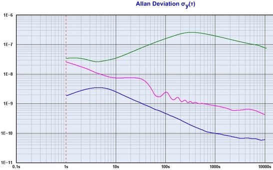
The upper curve shows the performance of the original 60-TF one day where the signal got so low that the frequency wandered off for a while. The middle curve is what you get if you remove the frequency measurements for the period of time while the frequency was off, just to give an impression of the deviation while the 60-TF remained in lock.
The lower curve is the Allan deviation for the receiver after it got modified as described above (no frequency data points were left out).
In all cases, the measurement session was done during daytime. The original 60-TF had so serious issues with weak signals that it did not make sense to pull it through prolonged testing.
Results for the updated design from longer sessions spanning over a number of days will follow.
In conclusion, the modifications have provided
The modifications had a significant impact on the frequency variations and the Allan deviation, as shown in the figure from runs with TimeLab 1.2 and the HP 5334B as counter using Z3805A as reference. For obvious reasons, the measurements were not done on the same day, so the differences between the graphs should not be interpreted as an accurate measure of the improvements. However, the trend is very clear.
- Cool and safe operation
- A mechanically stable chassis
- The possibility to run over several days and nights without wandering off
- Less 1 Hz frequency bumps
- Better Allan deviation over all time intervals
- Better time code extraction
- A more useful front panel
- Improved interfaces
The modifications had a significant impact on the frequency variations and the Allan deviation, as shown in the figure from runs with TimeLab 1.2 and the HP 5334B as counter using Z3805A as reference. For obvious reasons, the measurements were not done on the same day, so the differences between the graphs should not be interpreted as an accurate measure of the improvements. However, the trend is very clear.
Acquisition assistance for the 60-TF
Low bandwidth and quick acquisition are two conflicting requirements. In the first rebuild of the 60-TF a delicate tuning of the crystal oscillator was required to minimize the acquisition time. This is, however, not a robust solution, as aging or anything else distuning the crystal oscillator eventually will increase the acquistion time, much likely beyond acceptable limits. The rule-of-thumb is that the pull-in time of a 2nd order PLL gets 4 times higher when the initial frequency error is doubled, but gets 8 times higher when the loop bandwidth is halved. With a loop bandwidth of about 0.1 mHz an initial frequency error of 0.1 ppm the pull-in will require about 1,500 seconds, or slightly less than half an hour. However, an initial error of 1 ppm will result in a pull-in time of some 150,000 seconds, or well over a day. A means of acquisition assistance is essential if an acceptable acquisition time must be guaranteed.
I see this as a part of the explanation why off-air receivers never were too great: If the PLL can reach lock by itself within a reasonable timeframe by simple pull-in, the loop bandwidth will have to be so large that it prevents good performance. If you require good performance, you need narrow loop bandwidth plus some circuitry to allow the loop to obtain lock before you reach retirement.
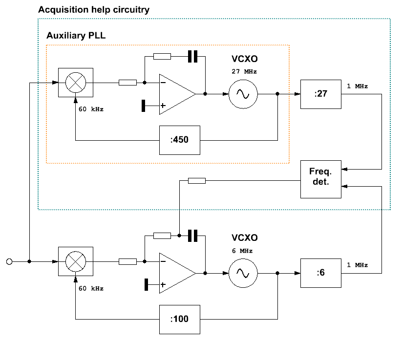
So, what's the right approach for an acquisition help circuitry when the MSF transmitter keys off the carrier, and propagation issues inevitably pollute the signal? The literature describes different frequency detectors or adaptive bandwidth techniques that can be used for speeding up the acquisition. I have selected a solution where an auxiliary PLL and a frequency comparator are used to control the integrator in the main PLL. The auxiliary PLL works independently of the main PLL and essentially cleans up the incoming signal to provide a continuous clock signal for frequency comparison. This is robust, cheap, and can be hooked up to assist almost any existing PLL. The auxiliary PLL has a wider bandwidth than that of the main PLL and has thereby a significantly shorter pull-in time. The frequency comparator is a transition direction detector with automatic time-out. The transitions are compared between the 1 MHz clock from the main PLL and a 1 MHz tick derived from a 27 MHz VCXO for the auxiliary PLL. The frequency detector is designed to time out when the frequency difference is about the same as the lock range of the main PLL.
I see this as a part of the explanation why off-air receivers never were too great: If the PLL can reach lock by itself within a reasonable timeframe by simple pull-in, the loop bandwidth will have to be so large that it prevents good performance. If you require good performance, you need narrow loop bandwidth plus some circuitry to allow the loop to obtain lock before you reach retirement.
So, what's the right approach for an acquisition help circuitry when the MSF transmitter keys off the carrier, and propagation issues inevitably pollute the signal? The literature describes different frequency detectors or adaptive bandwidth techniques that can be used for speeding up the acquisition. I have selected a solution where an auxiliary PLL and a frequency comparator are used to control the integrator in the main PLL. The auxiliary PLL works independently of the main PLL and essentially cleans up the incoming signal to provide a continuous clock signal for frequency comparison. This is robust, cheap, and can be hooked up to assist almost any existing PLL. The auxiliary PLL has a wider bandwidth than that of the main PLL and has thereby a significantly shorter pull-in time. The frequency comparator is a transition direction detector with automatic time-out. The transitions are compared between the 1 MHz clock from the main PLL and a 1 MHz tick derived from a 27 MHz VCXO for the auxiliary PLL. The frequency detector is designed to time out when the frequency difference is about the same as the lock range of the main PLL.
|
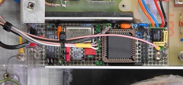
The acquisition help circuitry was rushed together on a small double-sided prototype board. The CPLD, an Altera EPM3064ALC44-10N, contains all the counter and logic functions described in VHDL. The VCXO is an older off-the-shelf 27 MHz model from Valpey-Fisher (now CTS Valpey).
|
|
This is the block diagram of the acquisition help circuitry and how it's connected to the existing receiver PLL. The connection to the control amplifier of the receiver PLL ensures that the frequency detector only contributes to the integrator part, not to the proportional part.
Key parameters for the auxiliary PLL: Loop bandwidth = 0.21 Hz Damping factor = 0.72 Lock range = 0.3 Hz = 5 ppm Pull-in time @ 1.5 kHz initial error (about full VCXO range) = 165 s Pull-in time @ 270 Hz (10 ppm) = 5.3 s |
|
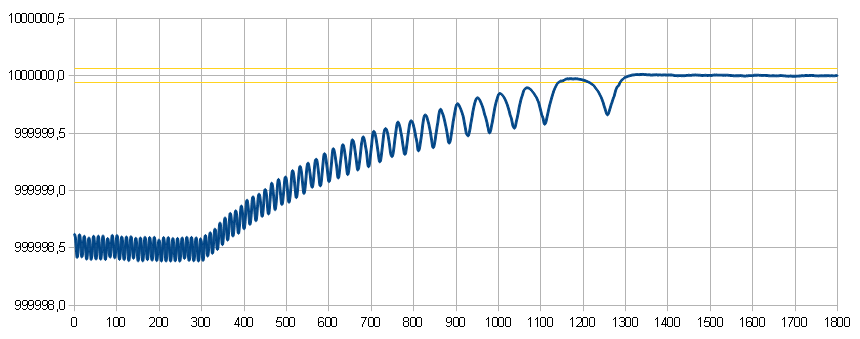
This is a demonstration of the function of the acquisition assistance circuitry added to the 60-TF. The graph shows the frequency of the 1 MHz output over half an hour.
Just before the measurement the integrator of the main PLL was nulled, and the acquisition assistance circuitry was intentionally disabled. After 300 seconds the acquisition circuitry was manually switched on, with a clear, steady pulling effect as the result. The output of the acquisition circuitry is automatically shut off, in this case at 1302 seconds after start. From that moment there are no cycle slips as the main PLL is now within its lock range, shown as the lines in yellow. Without the acquisition help the prospects of obtaining lock seem utterly bleak. The initial frequency error is close to 1.5 ppm, so we could expect the pull-in to take around 6 days, if we dare to boldly disregard offset changes, temperature effects and further aging during that time. With the acquisition help circuitry that time is reduced to something close to a quarter of an hour. For my Spectracom 8160A a similar acquisition assistance circuitry was made, based on the results from the tests with the 60-TF. Details are found here. |
