EDC E100RC DC millivolt reference source
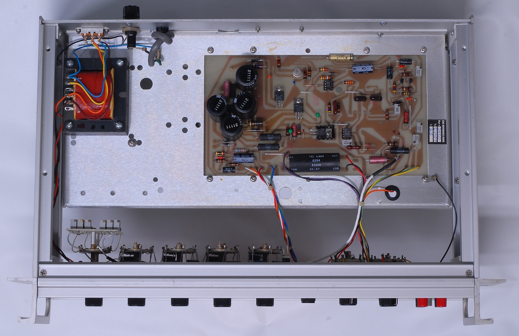
Above: The inside of the E100RC. The power cord has been cut as I was about to replace it with a proper IEC power inlet.
The 1N829A reference zener is the orange component located closest to the voltage label. The component placements in this particular unit do not correspond to the service manual I have retrieved from the Internet, so EDC or Krohn-Hite clearly made changes through the life cycle of the E100RC. Based on the date codes on various components, this unit was manufactured by the end of 1987 or later. |
The name of the E100RC is somewhat misleading, because the E100RC features two voltage ranges, one 100 mV range (0 - 111.11 mV) with 1 µV steps, and a 10 V range (0 - 11.111 V) with 100 µV steps. For both ranges one may activate a fine adjustment, ±0.1 µV in the 100 mV range, and ±10 µV in the 10 V range.
The design is quite simple, which makes repair easier, and facilitates modifications for that matter. There are only 6 resistors in each decade, so the value required is made from series/parallel combinations. This saves resistors, but requires that the trimmer resistors for the most significant decade are adjusted in the right order, as described in the service manual. The OP37 used as the op-amp in the inverting amplifier does not have any stellar DC specifications, and will result in more drift and errors than the chopper amplifiers used in other EDC products. Perhaps the main selling point of the E100RC was the mV range, so that it was decided to relax the requirements for the 10 V range? The E100RC uses a 1N829A as reference, and is designed as an inverting amplifier with the decade resistors in the feedback branch. The current from the zener to the inverting input of the voltage setting op-amp should be 0.1 mA. If you want to replace the 1N829A with something fancier, you should change the resistance to match the new reference voltage. For instance, the ADR1399KHZ from Analog Devices has a a specified voltage between 6.75 V and 7.25 V so you would have to add about 5 to 10 kΩ in series with the existing scaling resistor. |
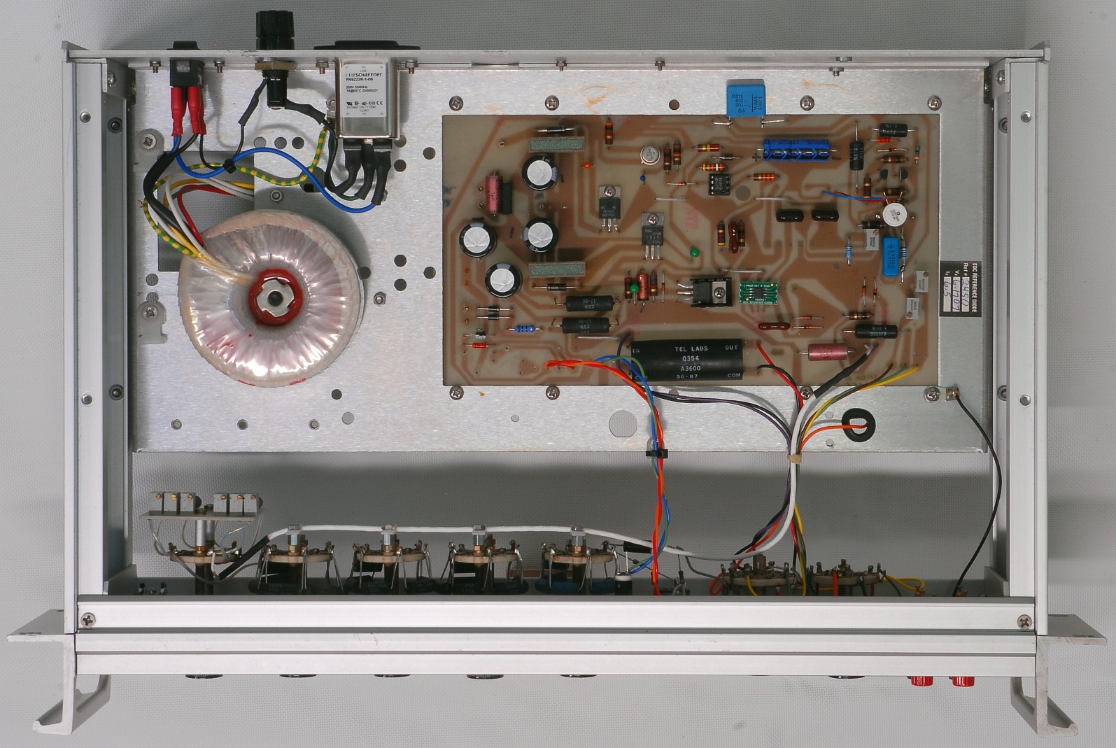
Above; The E100RC after the modifications to reduce the the ripple and the noise. Further reduction of the ripple may be possible by shielding the transformer with a lid made of steel plate.
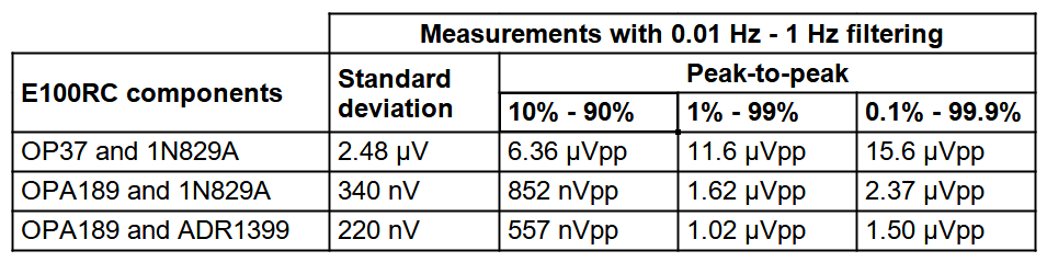
Above: Improvements of the low-frequency noise by replacing the control amplifier OP37 with an OPA189, and then by replacing the reference 1N829A with an ADR1399. In total, an improvement by an order of magnitude.
The measurements were made with an EM N1a nanovoltmeter connected to the E100RC through an RC highpass filter, using the widest filter setting of the N1a. The captured data was post-processed to limit the bandwidth before extracting statistics. 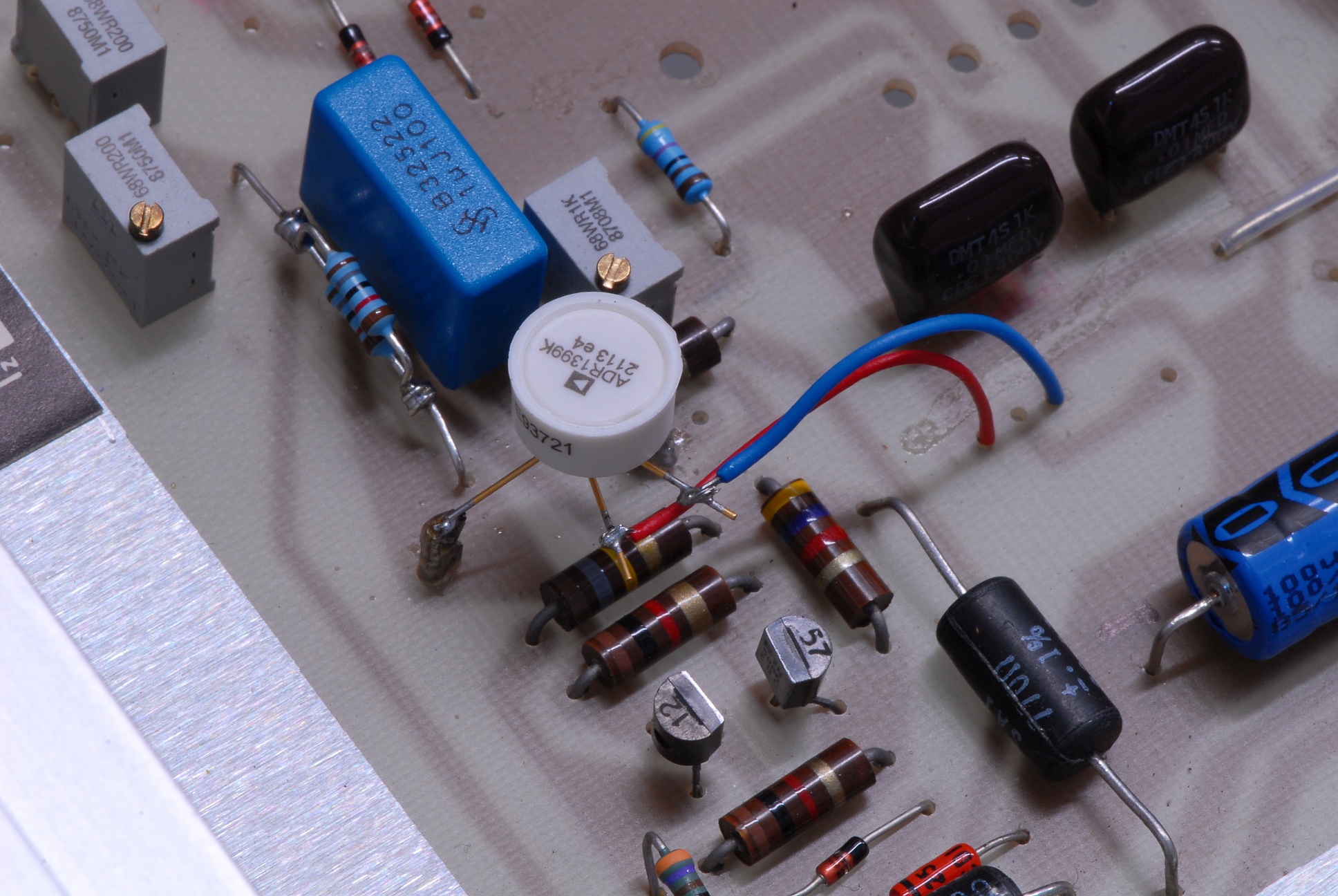
Above: Close-up of the ADR1399. The jumper has been replaced with two resistors in parallel. These resistors will be replaced with more stable, metal foil resistors,
|
I was originally planning to replace the 1N829A with the ADR1399, but the layout of the E100RC made me take a closer look at the noise and ripple performance first. As it turned out, there was room for improvement.
I measured the noise with a battery-powered EG&G model 113 preamplifier connected to an NI USB-4431 digitizer, powered from a laptop running on batteries. Hence, no mains ground loops. Sampling rate was set to 100 kHz, with 100 k samples aquired. Each of the peak-to-peak values below is the median value of 256 acquisitions. Measurements of the original design, which clearly had issues with ripple: Zero setting in the 10 V range: 245 µVpp / 49.2 µV RMS 10 V setting in the 10 V range: 47.8 µVpp / 10.2 µV RMS The stray field of the original mains transformer injects into the feedback loop, especially when the feedback impedance is low, which it is at the low settings, Also, there's some coupling from the mains switch and adjacent cabling to the inverting feedback loop, closely located at the leftmost switch. By replacing the original mains transformer with a toroidal mains transformer, by moving the mains switch to the back panel, by redesigning the offset circuitry and moving the 1 Ω resistor R51 to the front panel, the ripple and noise is reduced to: Zero setting in the 10 V range: 19.6 µVpp / 1.95 µV RMS 10 V setting in the 10 V range: 17.5 µVpp / 2.1 µV RMS In all, quite an improvement compared to the original design. The replacement of the mains transformer had by far the largest impact, and the effect was most pronounced at the low settings. The relocation of the mains switch and the modification of the offset circuitry improved the ripple at the high settings. After the reduction of ripple the control amplifier OP37 and the reference 1N829A were replaced with something more up-to-date: The OPA189 as control amplifier, mounted on an SO-8 adaptor board (Mouser 910-PA0001), and the ADR1399 as reference. The heater of the ADR1399 was connected between the +15 V and the -15 V rails, and the series resistors R25 and R2 were replaced with suitable power resistors in order to provide the start-up current for the heater without dipping the supply rails. The jumper R30 was replaced with a resistor to accommodate the slightly larger voltage of the ADR1399. C15 was replaced with a series connection of 1 µF and 5.1 Ohm, in accordance with the recommendations in the ADR1399 datasheet. The 200 Ohm trimmer R6 was replaced with a 1 kOhm resistor, so that the zener current is set at a fixed 3.35 mA. |
