Wavetek 148 repair
The Wavetek 148 is a versatile function generator for the service bench and other general purposes. The basic design is typical for the era with switched current sources charging a capacitor to produce a triangle, followed by a signal shaper to produce a sine wave. Additional features include sweep and an independent generator for modulation. It has for many years been the go-to generator on my lab bench if I wanted a signal where I could change frequency and level settings quickly and easily. An all-analog generator of this kind offers no keypads, menus or anything, just turn the pots and switches and you are fine. If frequency stability or distortion are a concern, you would definitely use other generators, but at the repair bench generators like the Wavetek 148 have a role to play, indeed.
A while ago I noticed that the output range attenuator started to behave badly, and as time passed I had to exercize the attenuator knob increasingly to ensure a stable output signal. A couple of rounds with contact cleaning spray did help, but were not able to eradicate the issue. Then, having tried a third round of contact spray that did not really work, I decided to do something more radical and replaced the attenuator switch with three relays.
A while ago I noticed that the output range attenuator started to behave badly, and as time passed I had to exercize the attenuator knob increasingly to ensure a stable output signal. A couple of rounds with contact cleaning spray did help, but were not able to eradicate the issue. Then, having tried a third round of contact spray that did not really work, I decided to do something more radical and replaced the attenuator switch with three relays.
|
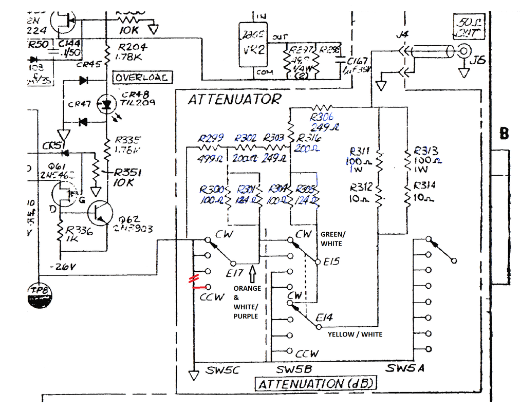
The schematic diagram of the attenuator in the Wavetek 148 manual has an error which is rather obvious once you realize how the attenuator is supposed to work. The corrected error is highlighted in red in the figure.
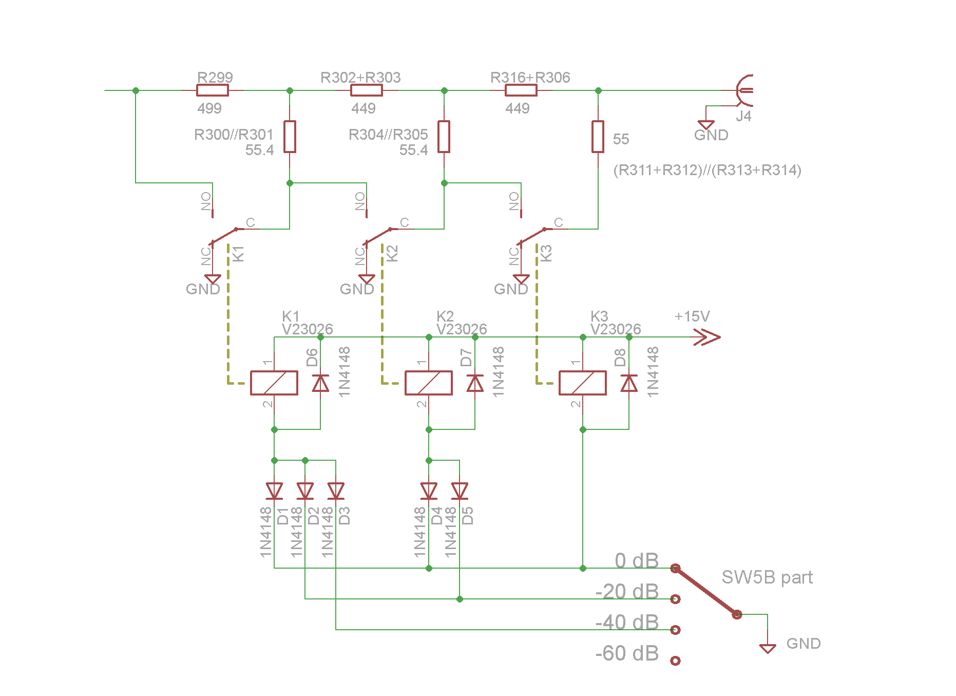
The diagram below clarifies the principle of the attenuator, and how the relays are powered. As default, the relays are unpowered and each of the three attenuator branches are grounded. Any issues with the rotary switch used to energize the relays will therefore result in maximum attenuation and a safe level. The relays used in this case are Siemens / TE Connectivity / AXICOM model V23026-A1003-B201 (15 V type), fixed with adhesive tape on the ground separator plate and on the board (see the pictures below). The power for the relays is taken from the +15 V rail at R145. Three positions of wafer B is used to pull the other side of the relay coils to ground. One of the positions of the wafer had to be unsoldered from ground, and the other two had to be disconnected from each other to allow control of the relays. The diodes ensure that the correct relays are being powered for each attenuator setting. |
|
|
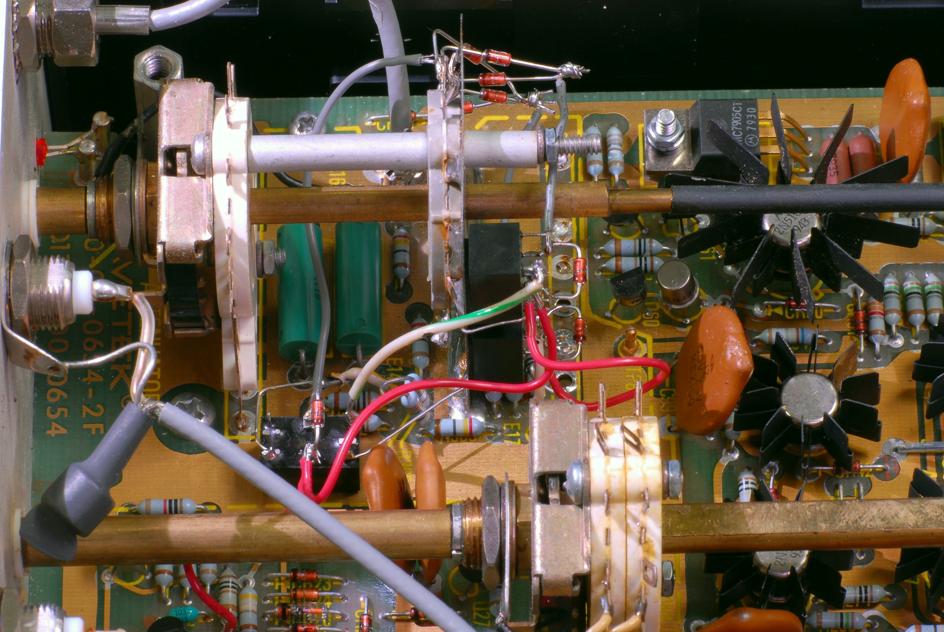
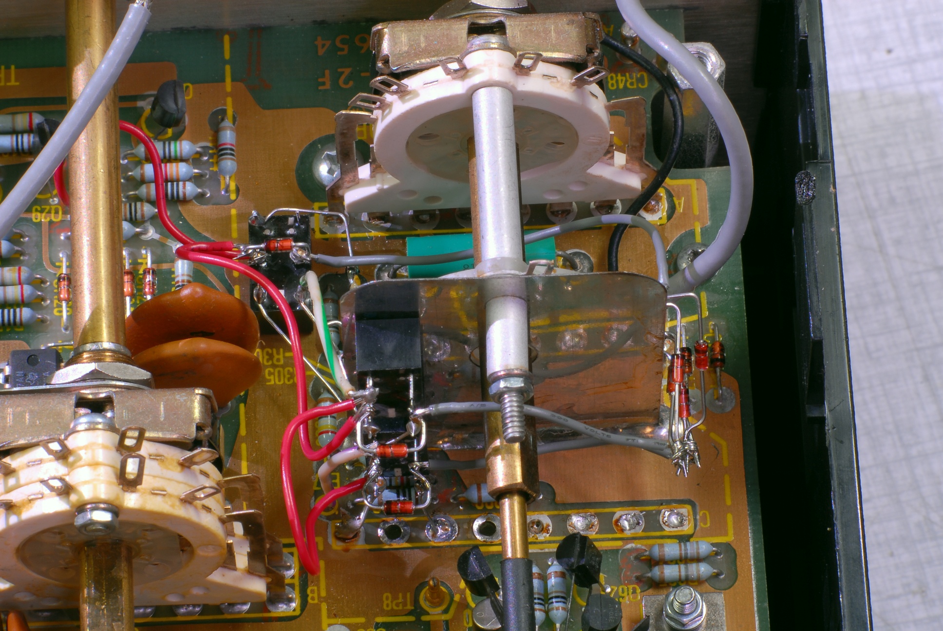
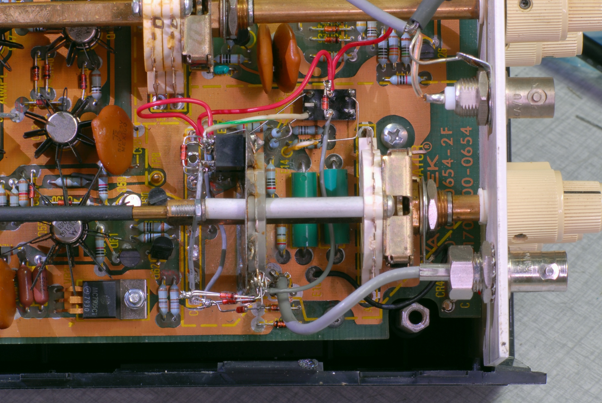
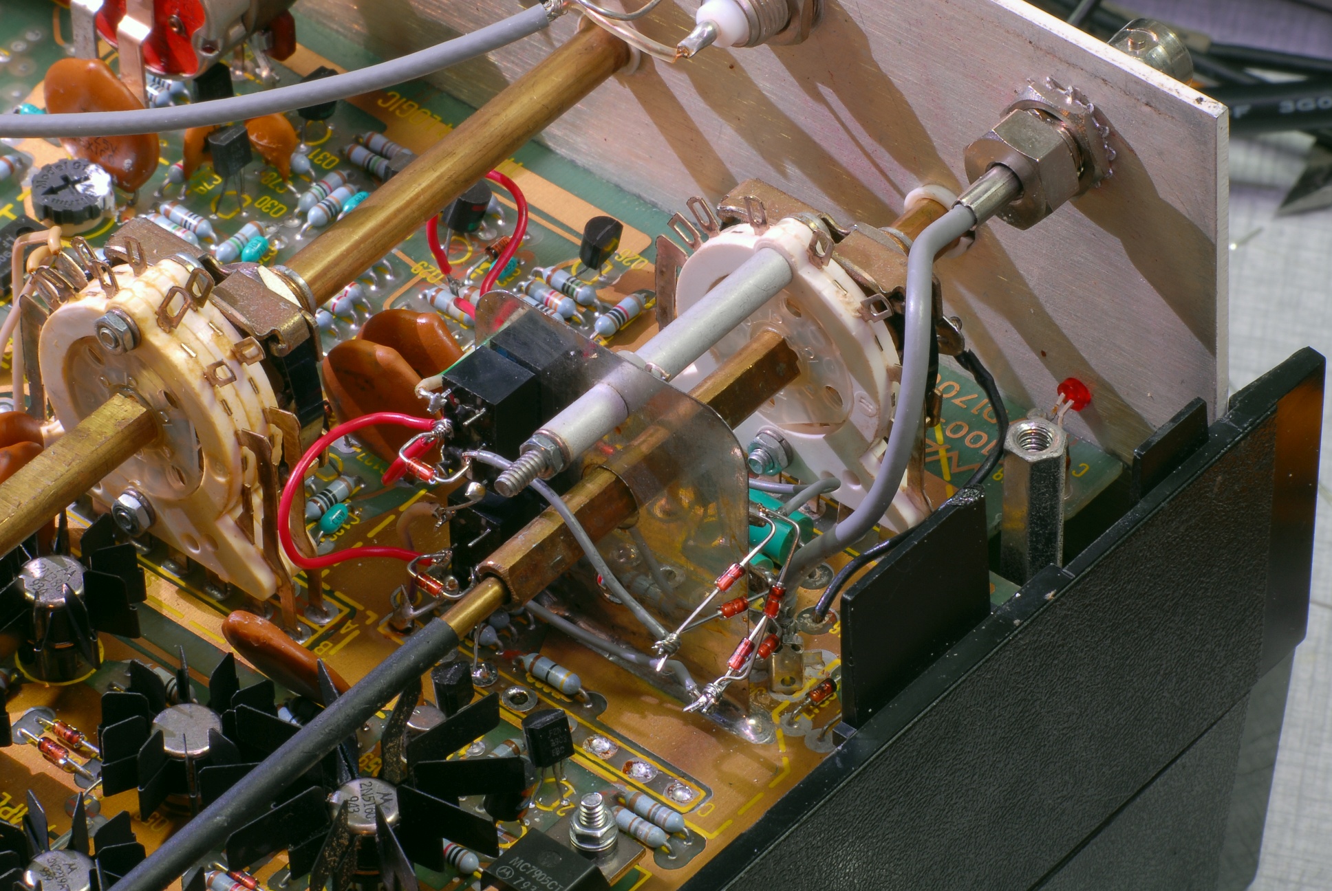
The pictures show the modification from different angles. Click on the pictures to get a higher resolution.
Wafer C has been completely removed. Still, there's not much space to work on, so be prepared to spend some 4 to 5 hours if you want to modify your own Wavetek 148. The red wires supply the +15 V rail for the relays. Note also that diodes are soldered across the coils to prevent voltage spikes when disconnecting the relay coils. |
