Various topics related to the measurement of impedance
|
|
Test fixture for impedance analyzers and LCR meters
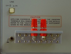
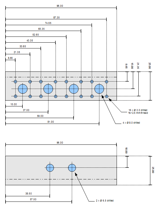
If you find one of the popular impedance analyzers or LCR meters, such as the HP 427xA family, on the second-hand market, a matching test fixture is typically not included. These test fixtures can be purchased separately, but the price tag can get close to that of the analyzer. However, if you just need to measure leaded components, you can with very limited effort make your own test fixture that works nicely with the classic 4-terminal BNC connection. The picture shows the test fixture I made for my HP 4276A LCZ Meter. I used quality BNC connectors from Suhner. These connectors have threaded mounting holes. The L-shape of the metal bracket gives a vertical orientation of the binding posts which I find more useful than the traditional horizontal orientation. The short connections allow full compensation by the open/short calibration routine. The trick is to measure out carefully where to drill, and only tighten the screws after the connectors have been mated gently with the BNC terminals of the analyzer. According to the Agilent Impedance Measurement Handbook (part no. 5950-3000) the distance between the BNC terminals is 22 mm. This handbook is recommended reading for anyone that has an interest in impedance measurements, by the way. |
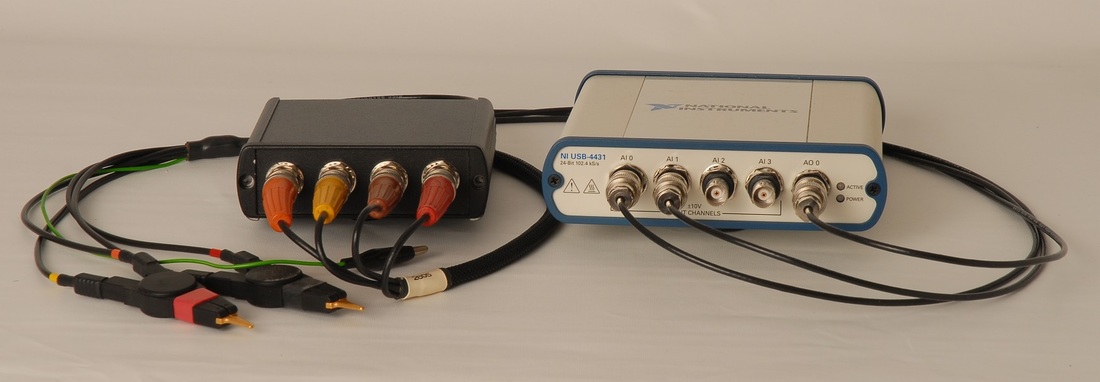
The adaptor prototype connected to NI USB-4431 and a set of Kelvin test leads from Wayne Kerr.
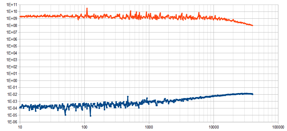
An impedance sweep from 10 Hz to 40 kHz with USB-4431, with open (orange) and shorted (blue) terminals. At these extremes, the response is determined by parasitics, channel separation, and channel noise.
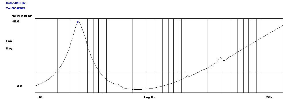
A bass driver (RCF L8/011) measured with the HP 3563A dynamic signal analyzer in combination with the impedance adaptor. The 3563A was set to a swept sine frequency response. The measurement was multiplied with the value of the scaling resistor, in this case 1 kΩ.
|
|
The IM6 Megohmmeter
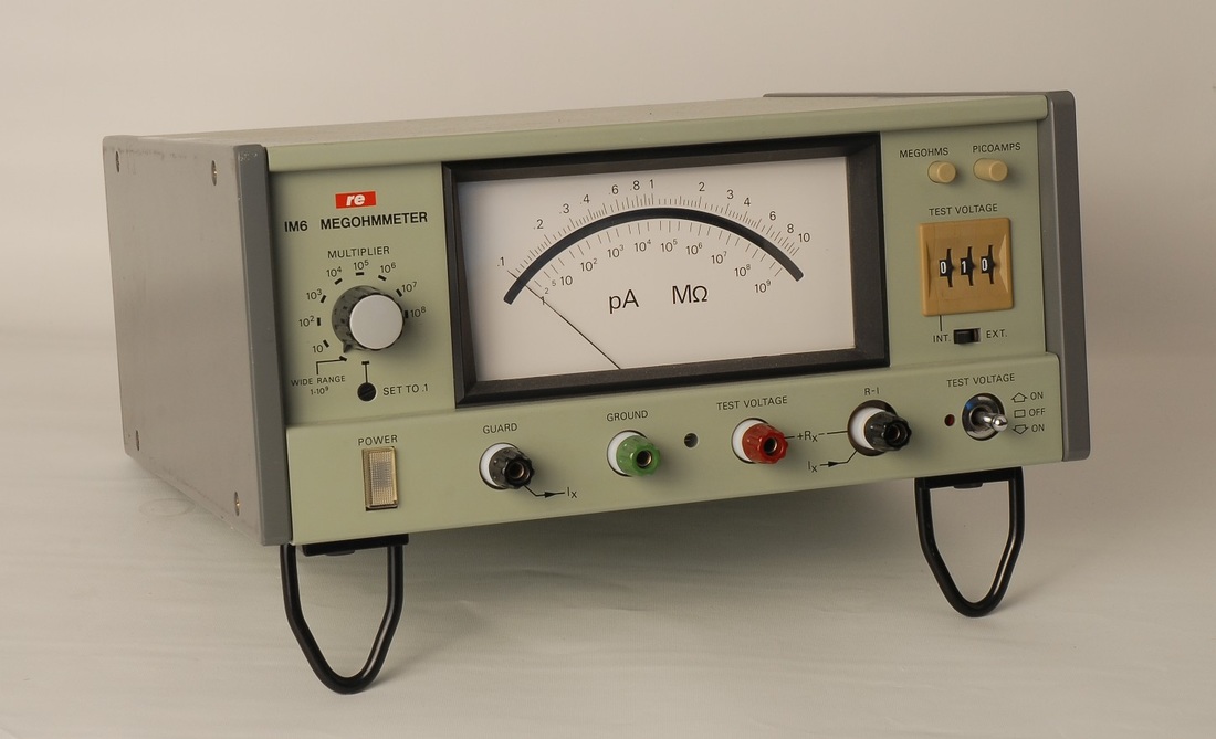
For high-impedance and capacitor leakage measurements I use the rarely found, somewhat aged but still highly useful IM6 from the Danish company RE. The company is no longer around, but I've got the service manual plus a few spare parts to keep the unit operational for some time to come. The IM6 measures down to 1 pA at up to 1kV test voltage. Other, more modern instruments outperform the IM6 by orders of magnitude, but it still does a good job at checking capacitors. One recurrent use is to select capacitors for analog control amplifiers for PLLs to maximize the time constant. Another typical use is to carry out leakage checks on safety capacitors. |
|
HP 4328A Milliohmmeter
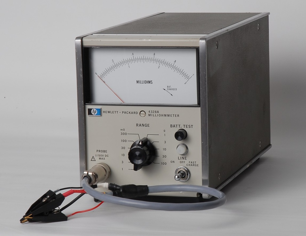
The 4328A seems to be a very popular instrument, based on the sales prices on the second hand market. Note that the 4328A went through a number of changes, and everybody tries to get a model with as high serial number as possible. I was lucky and got a very late model. All but the earliest models are designed to work with a dedicated test cable that can be disconnected from the box, and as a result, the majority of units being put up for sale do not have test cables included. However, you can with limited effort make your own test cables. Make sure to visit Brooke Clarke's pages (http://www.prc68.com/I/HP4328A.shtml), and the 4328A pages by the Green Bay Professional Packet Radio (http://www.qsl.net/n9zia/hp4328a/index.html). Get also a copy of the 4328A service manual, available from Keysight (previously Agilent, previously Hewlett Packard...) The cable in the picture was made with Hirose RM12BPE-5PH available from Digikey (P/N HR1732-ND with RoHS approval ) and Kelvin clips, also from Digikey (P/N 314-1128-ND). |
|
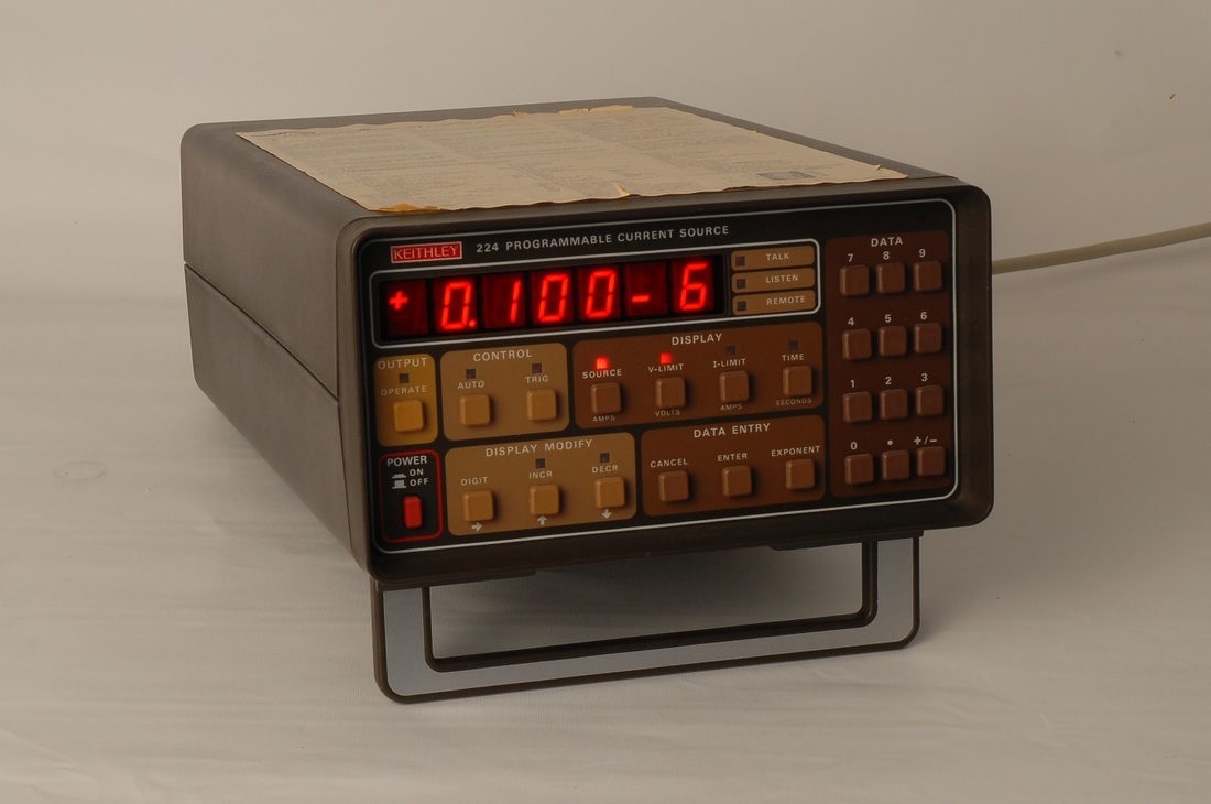
Keithley 224 Programmable Current Source
The 224 current source can be used for low resistance measurements: Apply a current through the device to be measured, with proper consideration of power and resolution, and measure the voltage drop with a sensitive voltmeter, such as the Keithley 181 Nanovoltmeter. Consult Keithley's "Low Level Measurements Handbook" for a good introduction to this and other measurement techniques. One drawback of the 224 is the not-so-common 2-lug Triax connector on the back, which I replaced with a 3-lug Triax in order to ease the cabling and avoid a 2-lug Triax adaptor. The larger diameter of the new 3-lug Triax required me to dismantle the rear panel and filter support assembly so that I could increase the size of the hole for the connector. This was a frustrating experience. Take a look at the fan assembly drawing in the 224 manual and you will perhaps understand why. I do not quite get why Keithley wanted to mount connectors on the filter assembly rather than on the rear panel. Anyway, the new 3-lug Triax connector made it all worthwhile. |
|
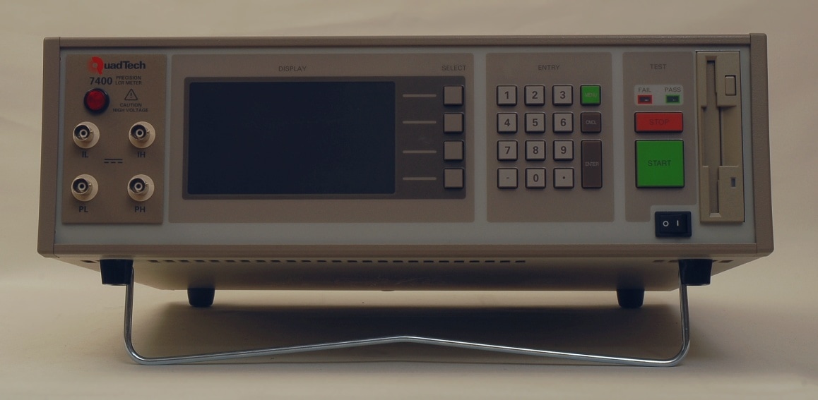
Quadtech 7400 Precision LCR Meter
This is one of the high-end performers within benchtop impedance meters. It offers 0.05 % basic uncertainty, a wide frequency range from 10 Hz through 500 kHz, and a variety of useful features for component characterization, impedance spectroscopy, etc. The frequency span down to 10 Hz even allows characterization of loudspeakers. For lower frequencies still I turn to my impedance measurement front end for DAQs and digitizers. The unit I got had issues with unexpected shifts of the readings in the order of some 200 ppm, and is currently undergoing some time-consuming checks. One working theory is that some reed relay could be wearing out, but the tests will hopefully tell. The plan is to carry out measurements of inherently stable components, such as the Genrad 1408, through a series of range changes to see if there's a revealing pattern in the readings. |
|
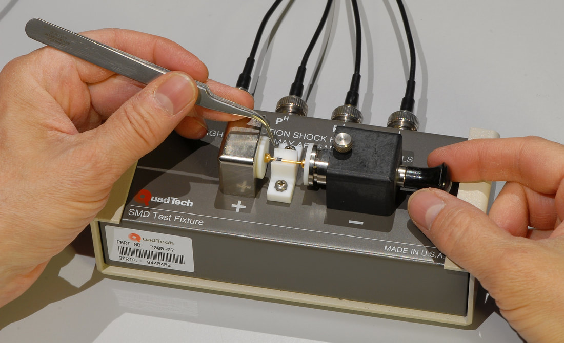
Quadtech 7000-07 Chip Component Test Fixture.
Test fixtures for surface mounted components are an important asset for testing today's electronics. A test fixture for leaded components is great, but there's no way around a proper test fixture for those SMDs. Maybe that's why they come with a huge price tag, even used ones. A model like the 16034E from HP / Agilent / Keysight is among those that you encounter most frequently on the second hand market, but there are alternatives. One is the Quadtech model 7000-07, now available from IET Labs. The unit shown here I got off an auction at a reasonable price, it was in impeccable condition, and included the original cables and the instruction sheet. It even had the production label attached. The 7000-07 accommodates the same component sizes as the 16034E. There are two major differences between the 7007-07 and the 16034E, though: The 16034E is designed to be connected directly to the instrument, and is specified for a max. frequency of 40 MHz. The 7007-07 is intended to be connected through cables, which I find very convenient when dealing with SMD components, but is specified for a max. frequency of just 2 MHz. |
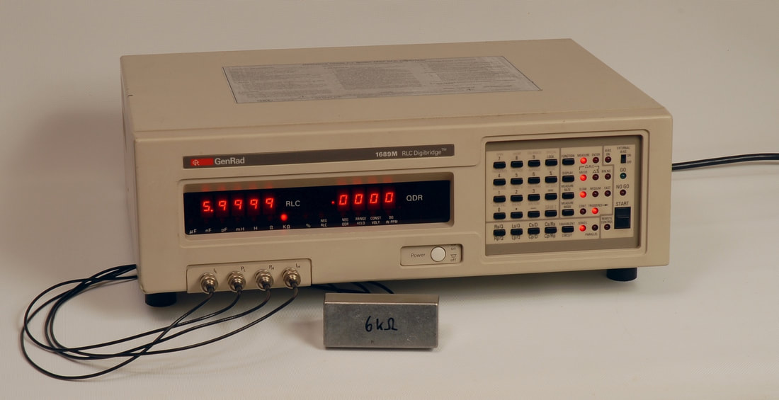
The 1689M measuring a 6 kΩ calibration resistor, after a successful repair session.
|
General Radio 1689M RLC Digibridge
The 1689M, originally made by General Radio, later by Quadtech and by IET Labs, stands out with its wide frequency range of 12 Hz to 100 kHz and a basic accuracy of 0.02 %. The younger model 1693M, which has now replaced the 1689M, offers a max. frequency of 200 kHz and additional impedance parameters. The 1689M and the 1693M are well built and are trusted in a number of impedance metrology applications. Note that the lowest uncertainty is obtained at 1 kHz and 'SLOW' rate setting only. The user is adviced to consult the manual for producing an error budget, and to follow the guidelines on how to enhance the accuracy. A convenient tool for calculating the "limits of error" is available at the IET web pages: For 1689: https://www.ietlabs.com/notes/digibridge_accuracy_calculator For 1693: https://www.ietlabs.com/notes/1693_digibridge_accuracy_calculator It's worth noticing that the calculators produce different results. The 1689M I found on the used marked at a fairly low price was not working correctly, alledgedly due to the RAM back-up battery. The repair session and the calibration that followed are described here. |
|
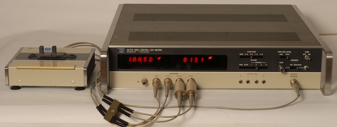
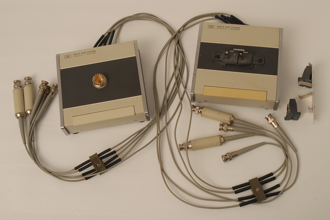
Hewlett Packard 4271A 1 MHz Digital LCR Meter
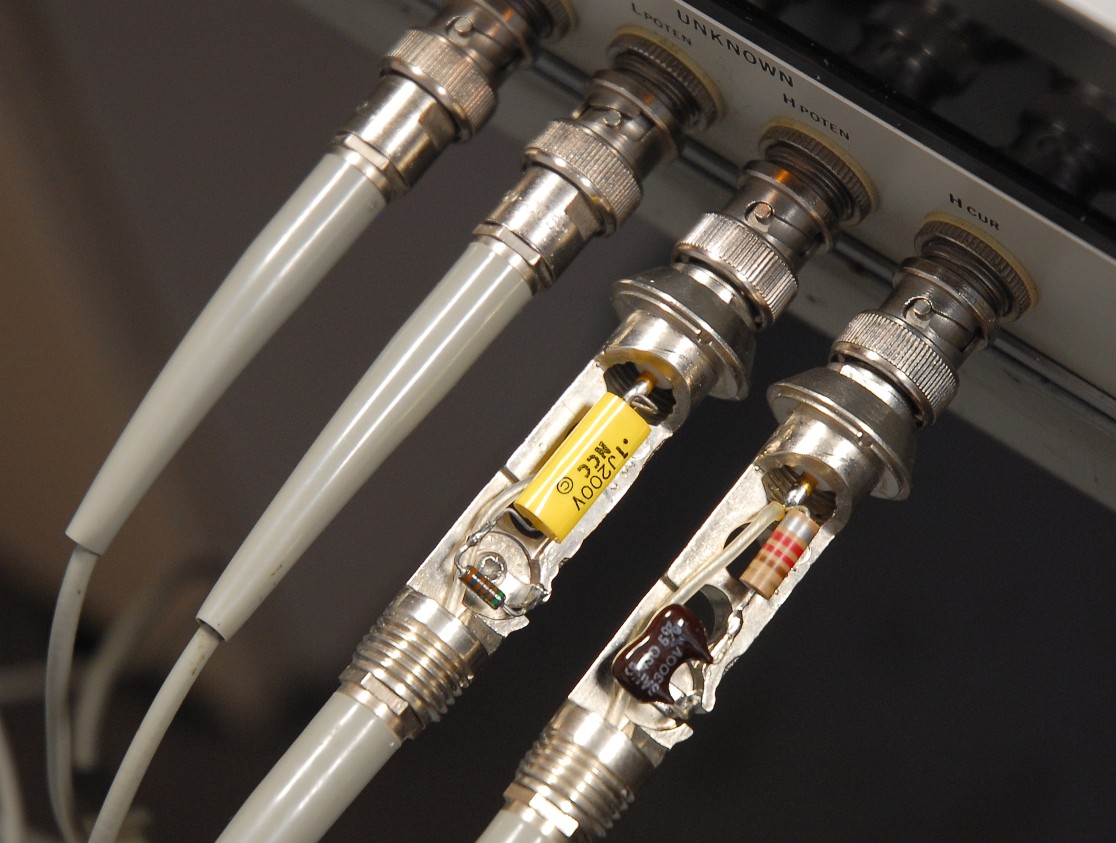
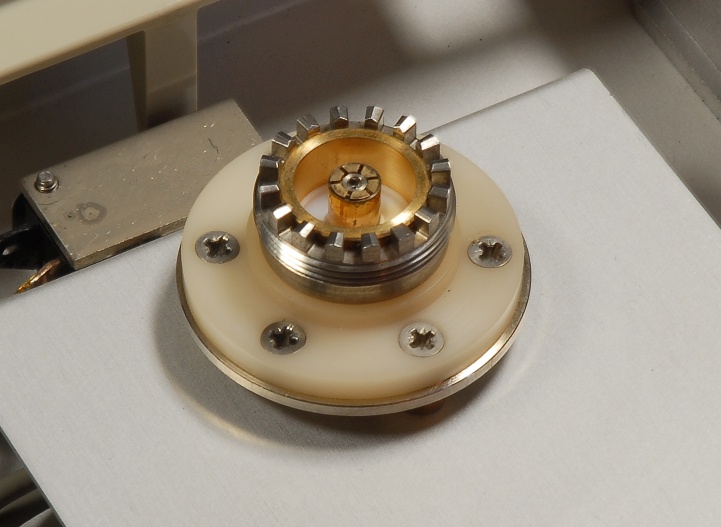
An early digital design, designed in Japan, based on two measurement principles: 1) Down-conversion from 1 MHz to DC in quadrature to two separate integrators, and subsequenct upconversion to 1 MHz to establish the balancing, and 2) A two-slope conversion with a fixed-time integration step followed by discharge to zero where the counting of the dischage phases provides the results. In spite of its age, it's still useful for checking ceramic capacitors and RF inductors. I got a defective unit from a garage sale and spent some hours debugging it. See the results on the 4271A repair pages. An LCR meter is of limited value only without the proper test fixtures. The picture shows the 16021A calibration fixture with the GR-900 connector, and the 16022A general purpose test fixture. The 16022A comes with two sets of inserts, one for radial components, and another for axial components. The insert set not in use is normally stored in the compartment accessible from the bottom. I also use the 16032A test leads with BNC connetors to connect the 4271A to custom test fixtures. If you want to make your own cables or test fixtures note that the 4271A requires a compensation network from center to GND for each of the two H terminals. Hcur: 220 µH (having about 7.8 Ω series resistance) + 430 pF 5%, in series Hpoten: 100 nF + 5.11 kΩ, in series The pictures below show the components of the compensation boxes with the protective barrel removed, and the isolated GR-900 connector inside the 16021A. |
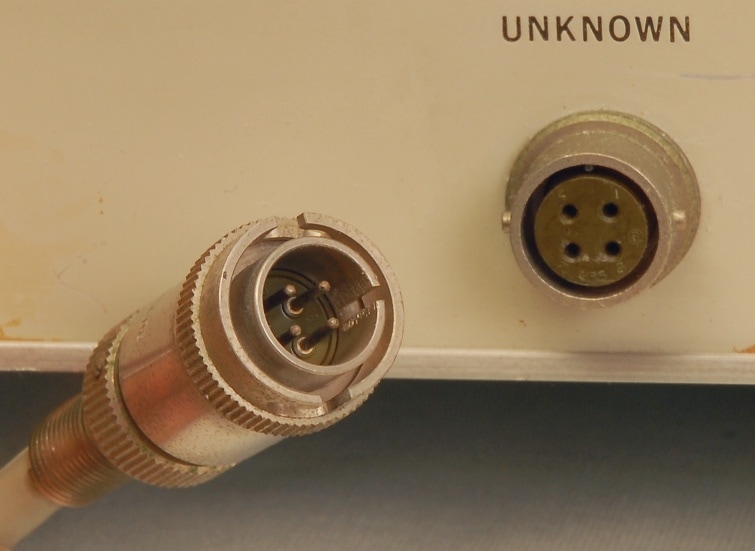
The connectors for the 4282A are from the Hirose RM series.
Chassis receptables J1 and J3 are RM12BRD-4S(71), available from Digikey (part no. HR1746-ND), or Farnell (part no. 2061616). The mating plug is RM12BPE-4PH(71), available from Digikey (part no. HR1731-ND), or Farnell (part no. 2061615). |
Hewlett Packard 4282A Digital High Capacitance Meter
For measuring large electrolytic capacitors this fairly old instrument is still something to consider. The option 001 offers leakage current measurement and an internal bias source up to 100 V, but the 100 V bias setting must be operated with more precaution than the 4282A manual cares to explain: When in 100 V bias operation, and having charged a capacitor, make sure to keep the function switch in the V or IL positions. Do not switch to the other functions, and do not switch to 10 V bias operation, as this will discharge the capacitor in an uncontrolled manner, and may possibly destruct or degrade the electronics in the discharge path. Do not count on the circuit fuse located on the back panel to offer the required protection. If you use the 100 V bias operation, set the bias toggle switch to OFF in order to discharge the capacitor, and turn down the bias voltage, before switching to other functions than V or IL. The best recommendation is in fact to avoid the 100 V bias setting in the first place. The 4282A is nicely built, but you need to be prepared for missing indicator lights, issues resulting from the internal 100 V bias, and bad contacts in relays. Take a look at the repair pages. |
|
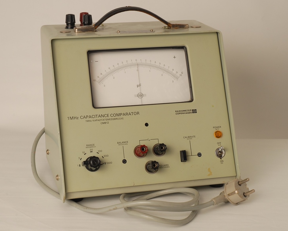
Radiometer CMB12 1 MHz Capacitance Comparator / Kapazitätsmessbrücke
This is a very rare piece of equipment, virtually impossible to retrieve any information about. The unit I got originates from the development lab of the Danish manufacturer, and is in working condition. Though a bit of a boat anchor, it actually serves a purpose of matching sets of capacitors, and the large analog display helps adjusting trimmers. Full scale reading is 1 pF through 1 nF, and the test voltage is about 100 mV RMS. With a pair of 1 nF capacitors, for instance, you may switch to the 1 pF range and read differences with 20 fF resolution. A short description of a brush-up session is found here. |
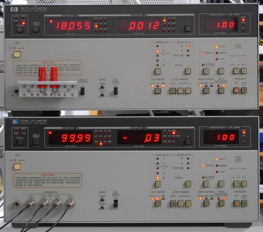
The 4277A on top of the 4276A. They are nice instruments, but they do take up space.
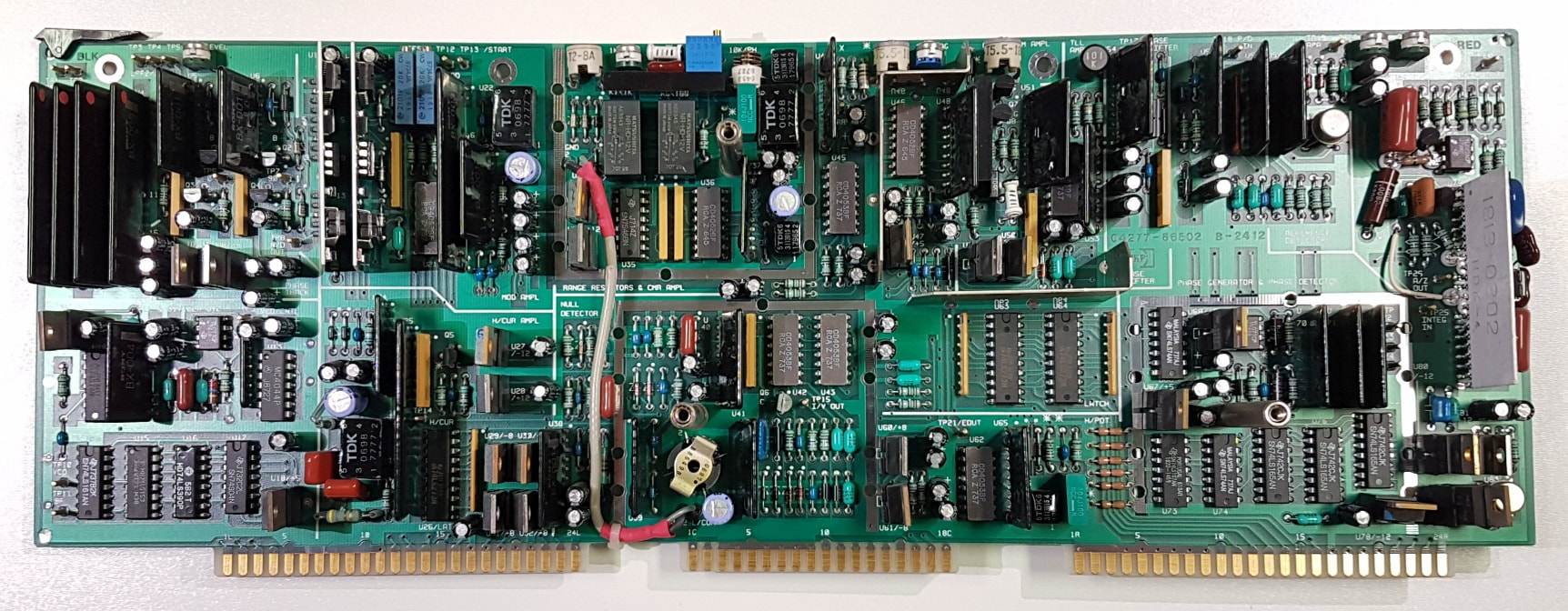
The 4277A analog board A2 with the shielding cans removed. Note all the Single-in-Line custom modules. The replaced R35 is located about the center at the edge of the board.
|
Hewlett Packard 4276A and 4277A LCZ meters
These two instruments are very similar in appearance, but cover different test frequency spans. The analog designs of the two are not quite the same: The 4276A is quite straightforward with a transimpedance amplifier connected to the low node, and the impedance is basically calculated as the ratio between the voltage over the DUT and the voltage from the transimpedance amplifier. If you think of the design as a bridge the balancing is ensured by the virtual ground of the transimpedance amplifier. In the 4277A the transimpedance amplifier is replaced by a more elaborate design: First, a set of concatenated amplifiers, and then a down-conversion stage in quadrature, two integrators, and an up-conversion stage in quadrature. Finally, a buffer drives the low node through a range resistor. This works better at high test frequencies which otherwise would challenge a single stage transimpedance amplifier. Hence, the balancing in the 4277A is ensured by integrators and not just by the gain of an op-amp. In order to save space the 4276A and 4277A feature several custom-made amplifiers, which is fine as long as they work and do not have to replaced with something else. In the 4277A the frequency conversion and the integration are handled by two identical custom modules. These two are not covered by black lacquer, like almost all other of the modules, so the components are visible. With all the gain preceeding these modules, the designers could settle for a simple design with an MC1496 for the down-conversion, a dual op-amp JRC4558 as voltage translator and integrator, and an MC1596 for the up-conversion. When I got the 4277A its was behaving weirdly: A reading of a 100 Ohm resistor could be either spot on, or it would be about 1 % too low. Measuring a 1 kOhm or a 10 kOhm resistor was even worse, with huge variations. Adding to this, the 4277A would only sometimes successfully go through its open compensation, but in most cases, it would not. Even stranger, by simply disconnecting and connecting the LCUR terminal repeatedly the 4277A could all of a sudden start to show the correct results. Looking at the schematics I strongly suspected the relays K1 and/or K2 to suffer from relay fatigue, but further investigations proved me wrong. I systematically measured the AC levels at a number of test points, and in particular at the nodes around U37 and its range resistors, both while measurements were correct and wrong. By going through the numbers, the culprit was found: The 100 Ohm trimmer R35! It had turned into a very unreliable open circuit that could make contact if it was subjected to a voltage transient, like the transient caused by connecting the LCUR terminal. R35 was replaced, and the 4277A was as good as new, measurement were stable, the open compensation could be done, and the instruments could be calibrated. |
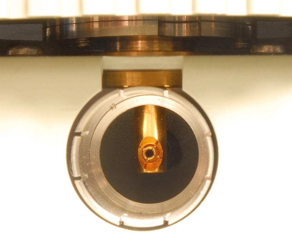
To the right: A rarely seen view of the contact area inside the 16099A.
|
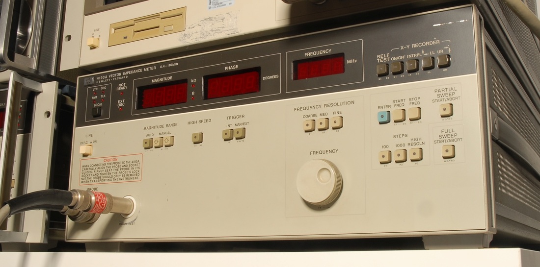
Hewlett Packard 4193A Vector Impedance Meter
The 4193A allows you to measure the impedance and its angle in the 400 kHz through 110 MHz frequency range. Thanks to the probe, the 4193A is great for in-circuit checks and ground-referenced measurements. The weak side of the 4193A is the limited frequency resolution which prevents it from being used on high-Q components, such as crystals. Also, it would have been nice if the 4193A had covered frequencies down to eg. 100 kHz. With the component adapter in the probe kit (04193-87001) you may measure leaded components. I have found the 4193A useful for characterizing EMC ferrite components and RF coils. An application in LabVIEW controls my 4193A to add flexibility, speed and data processing. For higher frequencies or better resolution I turn to the 4291A (see below.) The second picture shows the 16099A adapter for connecting the 4193A test probe to test fixtures with an APC-7 connector. The 4193A is frequently seen on the used market, but not often with the probe or probe kit included. The probe consists of a two channel sampling bridge with one current transformer, and should not be too difficult to replicate (though I did not have to try it, yet). If you're looking for a more up-to-date version of the 4193A, try take a look at the Trewmac Systems TE1000 RF Vector Impedance Analyzer (discontinued), or the newer TE3000/3001 models, which even extend the frequency range down to 30 kHz, thereby bridging the gap to common LCR meters. |

|
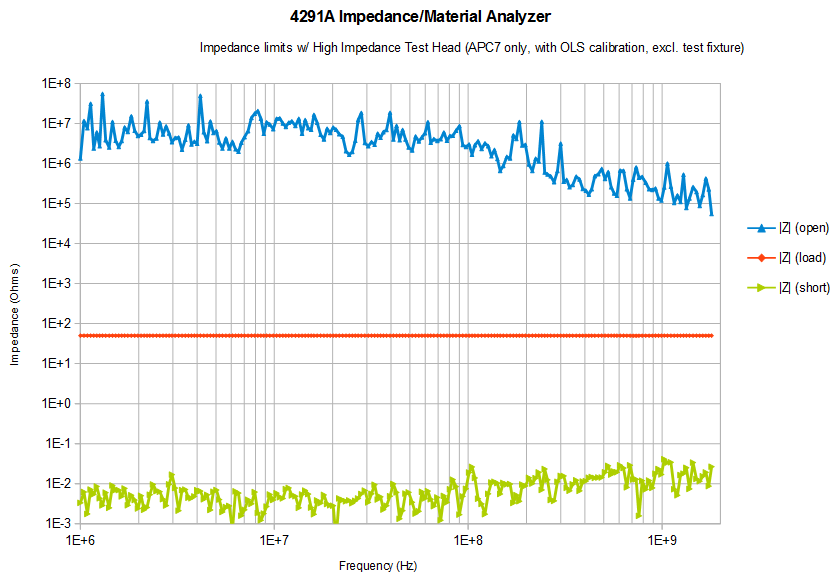
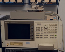
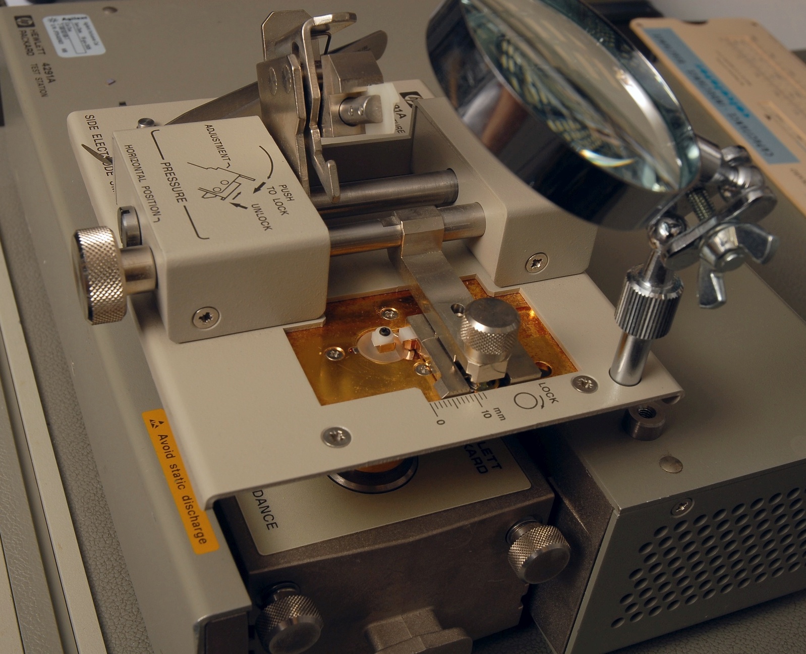
Hewlett Packard 4291A RF Impedance/Material Analyzer
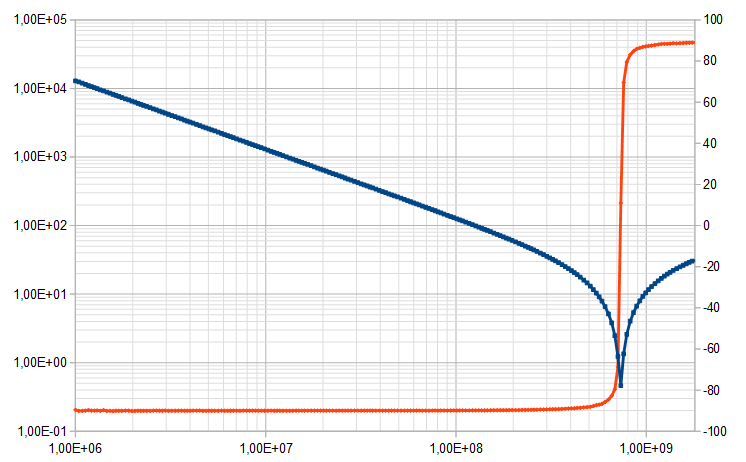
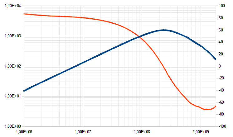
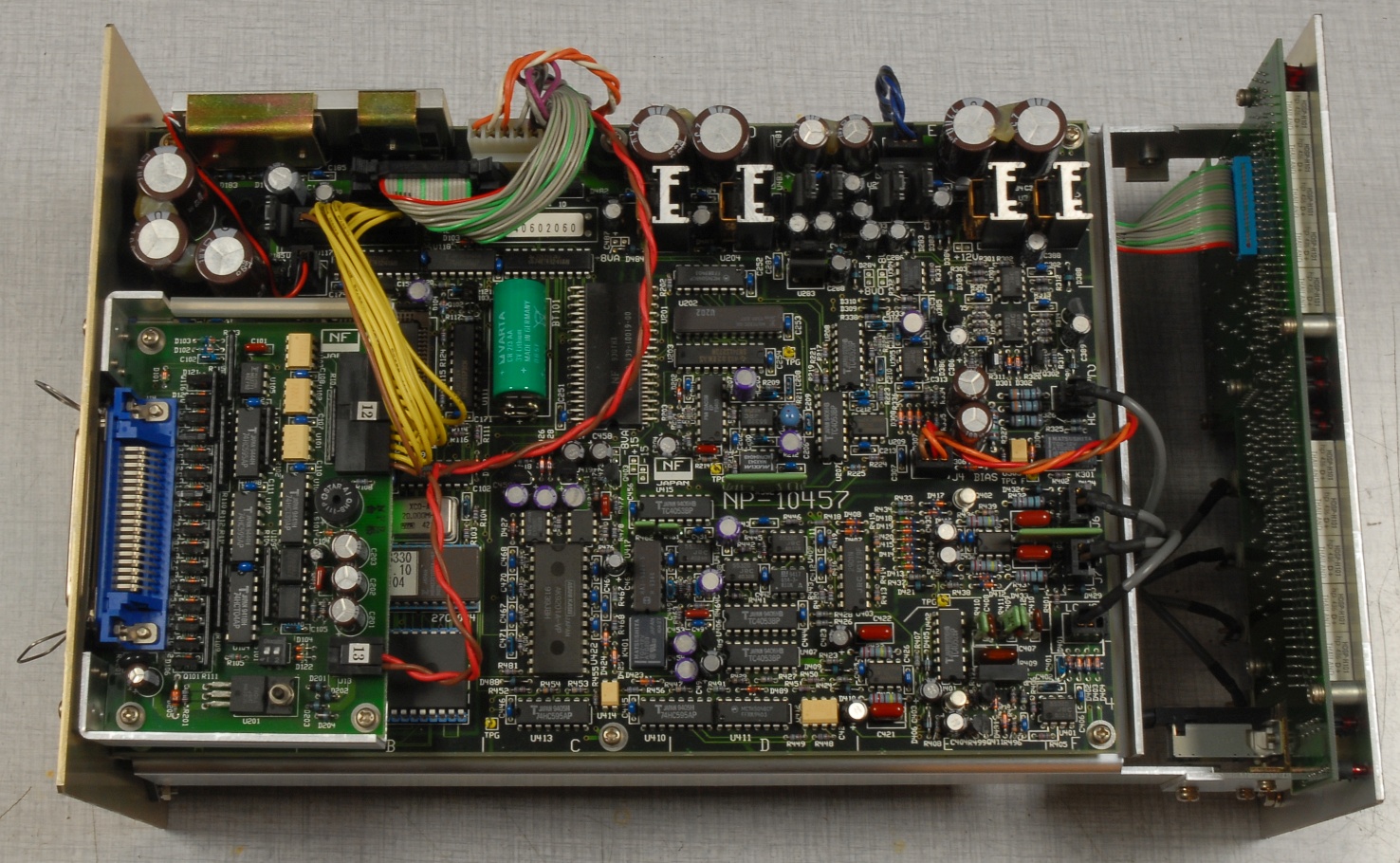
With this at hand you can measure impedances of devices from 1 MHz to 1.8 GHz with 1 mHz resolution, as long as the device being measured is accommodated by the test fixture you use for interfacing to the APC-7 connector. The 4291A is a powerful tool for characterizing components to give you the knowledge required for critical designs or RF circuitry. If you look for a 4291A/B on the second hand market keep in mind that without the test station and the test head, the 4291A is not of much use. Also, the right test fixture and a calibration kit are mandatory when working with the 4291A, but these seem to be sold separately by default. With some effort, and close attention to the fixture compensation described in the 4291A manual, you may design your own test fixture. Alternative fixtures, still good at 1.8 GHz, have been available from eg. Coilcraft. The 4291A and the similar 4291B provide clear advantages over the older 4191A RF Impedance Analyzer, both in terms of features, frequency span and resolution, but the 4191A is available at much lower prices than the 4291A/B. The graph below the picture shows the measured impedance limits of the 4291A equipped with a high-impedance test head, for a short and an open termination, after open/load/short calibration and applying fixture compensation. The measurements were made without fixture, however, to find the extremes at the APC-7 interface. The orange line represents the measured impedance for the 50 Ohm load. The last graphs show examples of actual impedance measurements from 1 MHz through 1.8 GHz, with the impedance (blue) and phase (orange) for a 12 pF SMD capacitor (size 0805), and for a common-mode coil, TDK part no. AGM 3225-102-2P-T001. Both measurements were made using the 16191A test fixture. The equivalent circuit for the capacitor reads 12.509 pF + 3.7674 nH + 457.85 mΩ. With a reading of 1.025 kΩ @ 100 MHz the common-mode coil is close to the specified 1 kΩ. One day, my 4291A stopped working. It turned out that it was the fan activity and over-voltage monitor for the second switcher in the Toko main power supply (HP part no. 04396-69040) which decided to turn off all but the +70 V and +25 V rails. I eventually cut out the SCR TH130 which got triggered falsely. Without this, an over-voltage situation on the +5 V rail is not discovered, so I checked and adjusted this rail before installing the Toko supply again. The pulse train from the fan worked as it should, by the way. While I had the Toko supply disassabled I replaced all electrolytic capacitors expect those of the mains rectifiers, and I replaced the old Schaffner FN370 IEC inlet with a new Schaffner FN382-6-21 inlet, just to avoid any unpleasant smoke-filled events when (not if) the old inlet decides to blow up. This IEC inlet does not have a voltage range selector, so I just removed the supply's cables for a voltage selector to allow operation at 240 V mains only (for 240 V mains operation these cables are not connected to anything). |
|
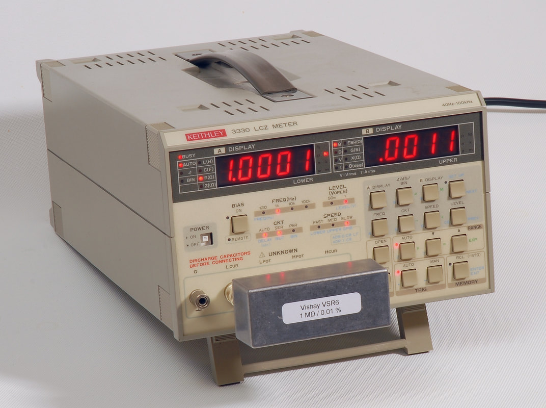
Keithley 3330 LCZ Meter
This neat design from Japanese manufacturer NF rebranded for Keithley offers 201 test frequencies from 40 Hz to 100 kHz. With so many LCR meters and impedance analyzers having 100 or 120 Hz as the lowest test frequency, the 40 Hz limit is an advantage. Still, one wonders why NF did not decide to go further down to allow characterization of loudspeakers, for instance. One issue to keep in mind with this family of LCZ meters: When the built-in lithium battery wears out, you need to replace it and carry out a full calibration through the GPIB interface, using the CAL.EXE calibration software available from Keithley. The 3330 also requires a DMM (Agilent 3458A or Fluke 8840/42A specifically!) The unit I found at a reasonable price had the two displays showing the 'EEEEE 22222' error message at power-up, the symptom of lost calibration due to a drained battery. However, the previous owner had also fried the output stage of the HCUR output, and the current converter stage of the LCUR input. I suspect this was caused by a charged capacitor! Though no schematics are available, I managed to locate and replace the defective components: The driver transistors for the output stage, and the protection diodes of the input stage. To carry out the calibration of the Keithley 3330 I run the CAL.EXE program from Keithley on an old HP Pavilion PC with Windows XP Professional and a National Instruments PCI-GPIB module. For the level measurement I use the Fluke 8842A multimeter. You need to follow the procedure in the calibration manual, but there's one thing the manual fails to mention: During the level measurements the HCUR and HPOT terminals need to be connected together. This is likely the function of the "SPECIAL JIG" mentioned in the calibration manual, but no details are provided. The figure 1 in the calibration manual also fails to show this connection. |
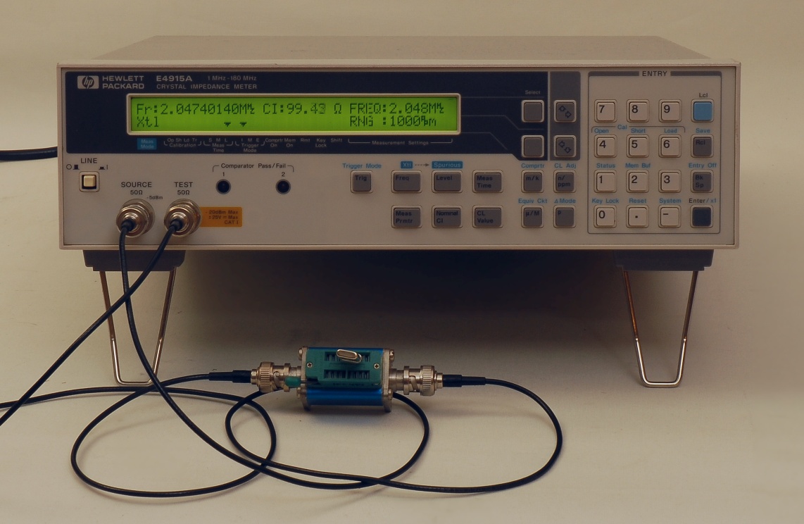
The E4915A at work with a DIY adaptor according to IEC 444 in a Sucobox from Suhner.
|
Hewlett Packard E4915A Crystal Impedance Meter
For measurements of crystals the E4915A is a convenient alternative to a network analyzer or vector voltmeter, and eliminates the manual parameter extraction. The enhanced model E4916A allows even testing at different drive levels, and includes an LCR measurement option. The E4915A and E4916A target specifically measurements according to IEC 444 / 60444 and therefore requires a proper PI-network test fixture. The fixture models from HP/Agilent/Keysight include 41900A, 41901A and 41902A, but these are rarely seen on the used equipment market. Other fixtures are available from companies like Saunders, Transat / Sansei Showa Co., Ltd., and Kolinker, but eventually you may have to make your own set of fixtures. Reliable testing of SMD crystals can be a pain, but Abracon comes to rescue with their variety of SMD crystal "test & burn-in" sockets with pogo connections. Should you need to test common leaded HC-18/U and the likes, Fischer Elektronik offers the PQ18 sockets. Note that measurements below 1 MHz are outside the scope of IEC 444 / 60444 due to the elevated crystal impedance level. Another test fixture in combination with a network analyzer or perhaps an acquisition module are required for this range. |
|
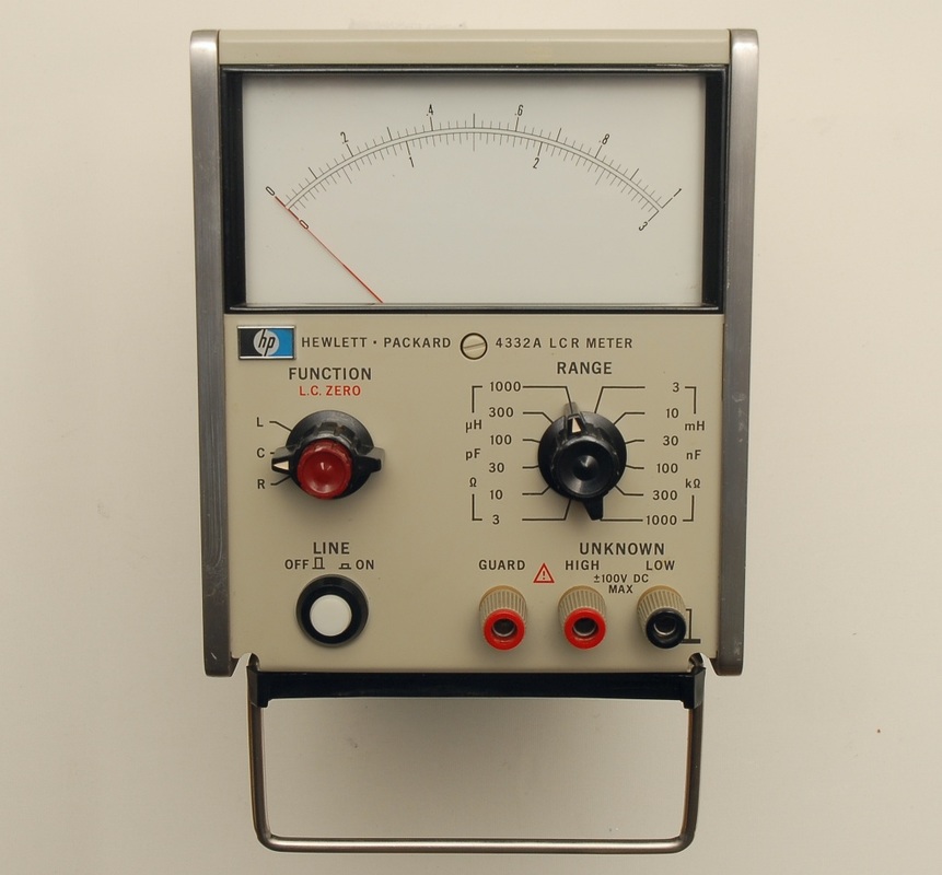
Hewlett Packard 4332A LCR Meter
For service and quick tests of components where accuracy is not a top-priority, this analog, old-school LCR meter from Hewlett Packard comes handy. The one shown here with serial number prefix 1848J is one of the later versions, produced around 1980. For the L and C measurements the 4332A applies either a 1 kHz or a 100 kHz test frequency. This, in combination with the guard terminal, allows the 4332A to measure down to 3 µH and 3 pF full-scale. The advantage of the analog scale is that one may see the effect of changes immediately, such as varying adjustable components. A DMM can be connected to one of the two DC outputs on the back for more reliable readings. The 16138A test leads are rare to come across, but you may easily make your own leads from three banana plugs, a piece of coax cable, a wire, and a pair of hooks or alligator clips of your own choice. Note, by the way, that the distance between the terminals allows Genrad type 1409 standard capacitors or ESI type SR1 standard resistors to be plugged in directly without the 16138A test leads. |
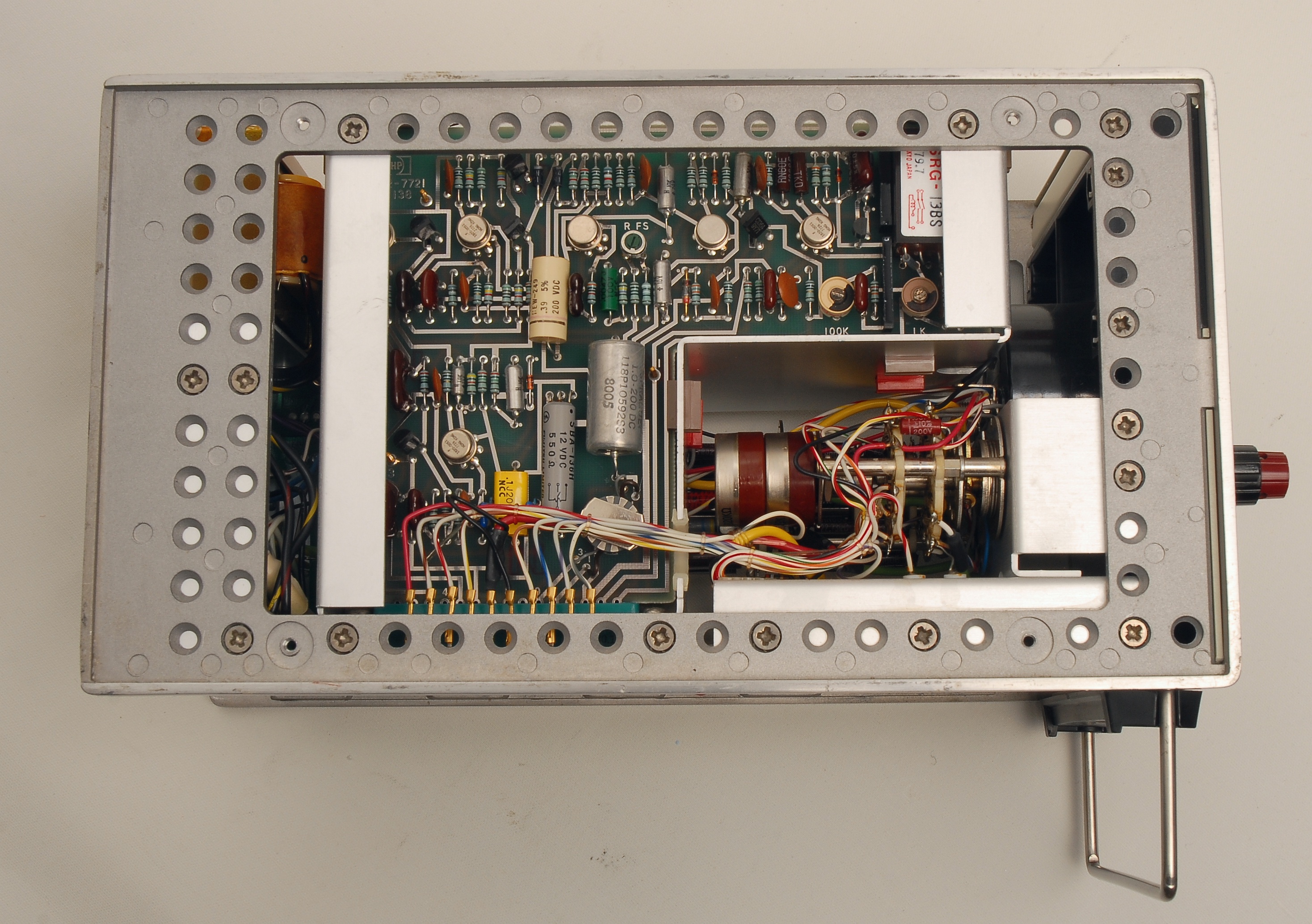
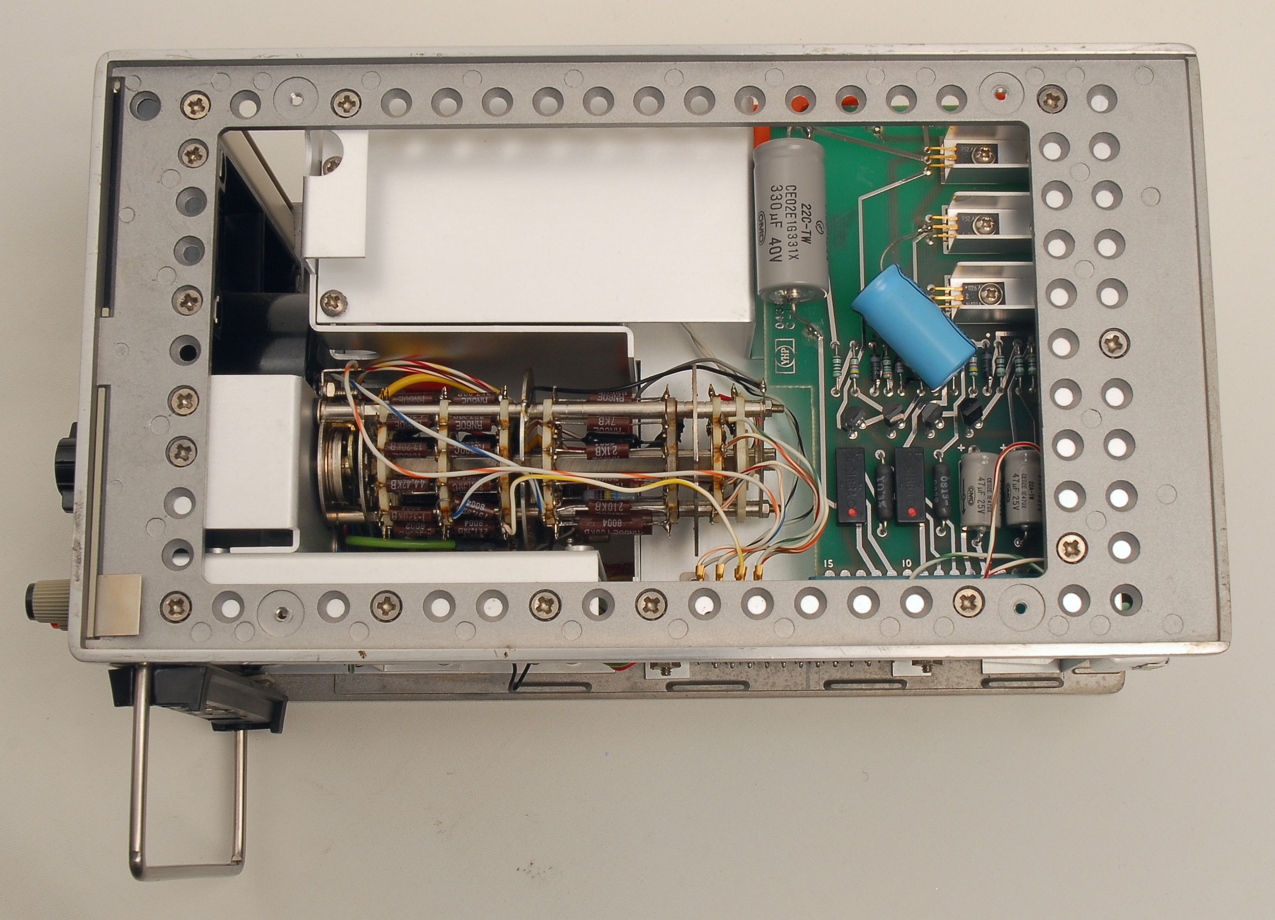
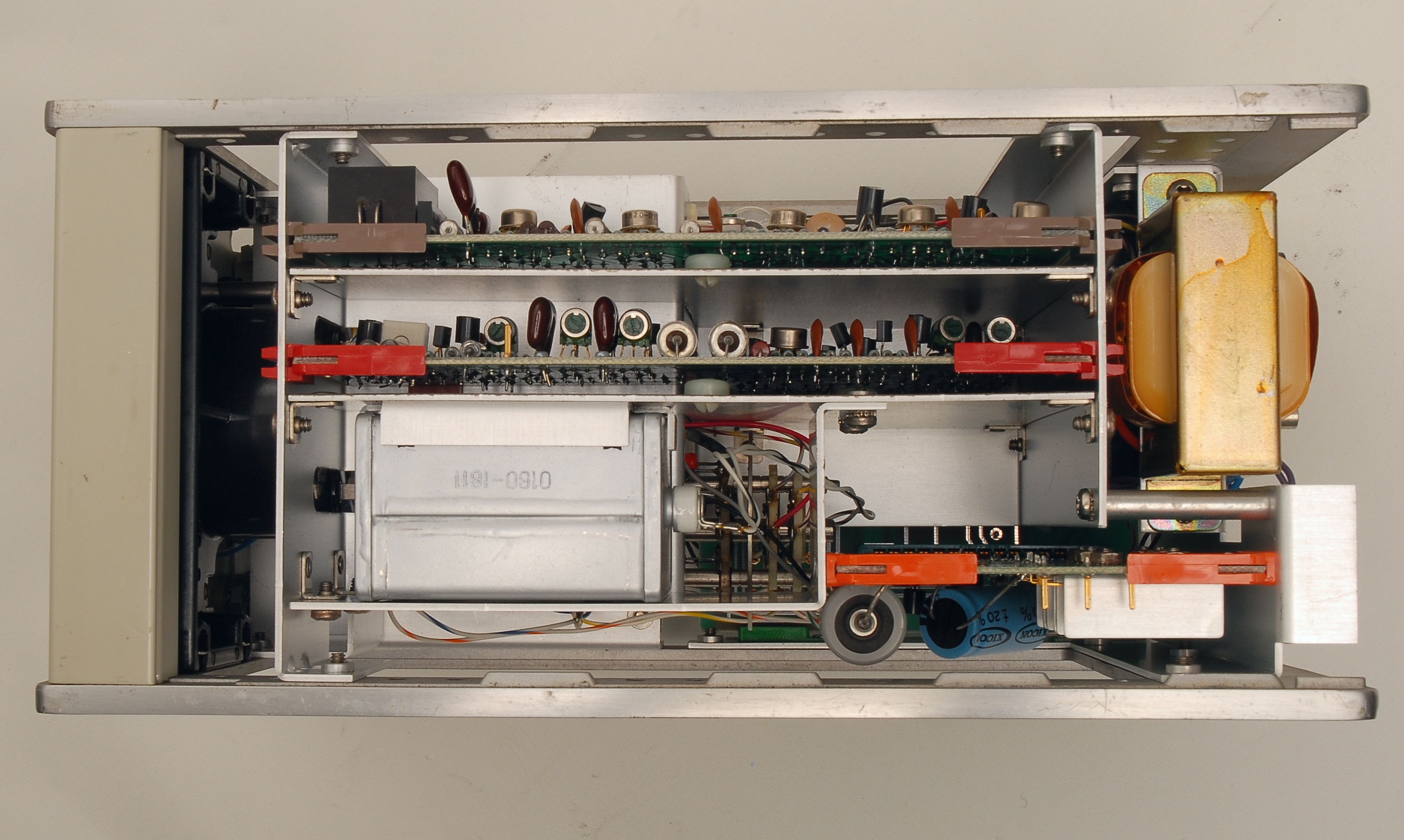
The service manual available on the Keysight web pages is a poor quality scan with pictures that provide too little information. If you click on the pictures below, you'll get access high-res pictures. If you wonder about the metal can in the middle, it's a 30 µF / 150 V metalized paper capacitor which permits an external DC bias voltage to be superimposed on the test signal.
|
|
|
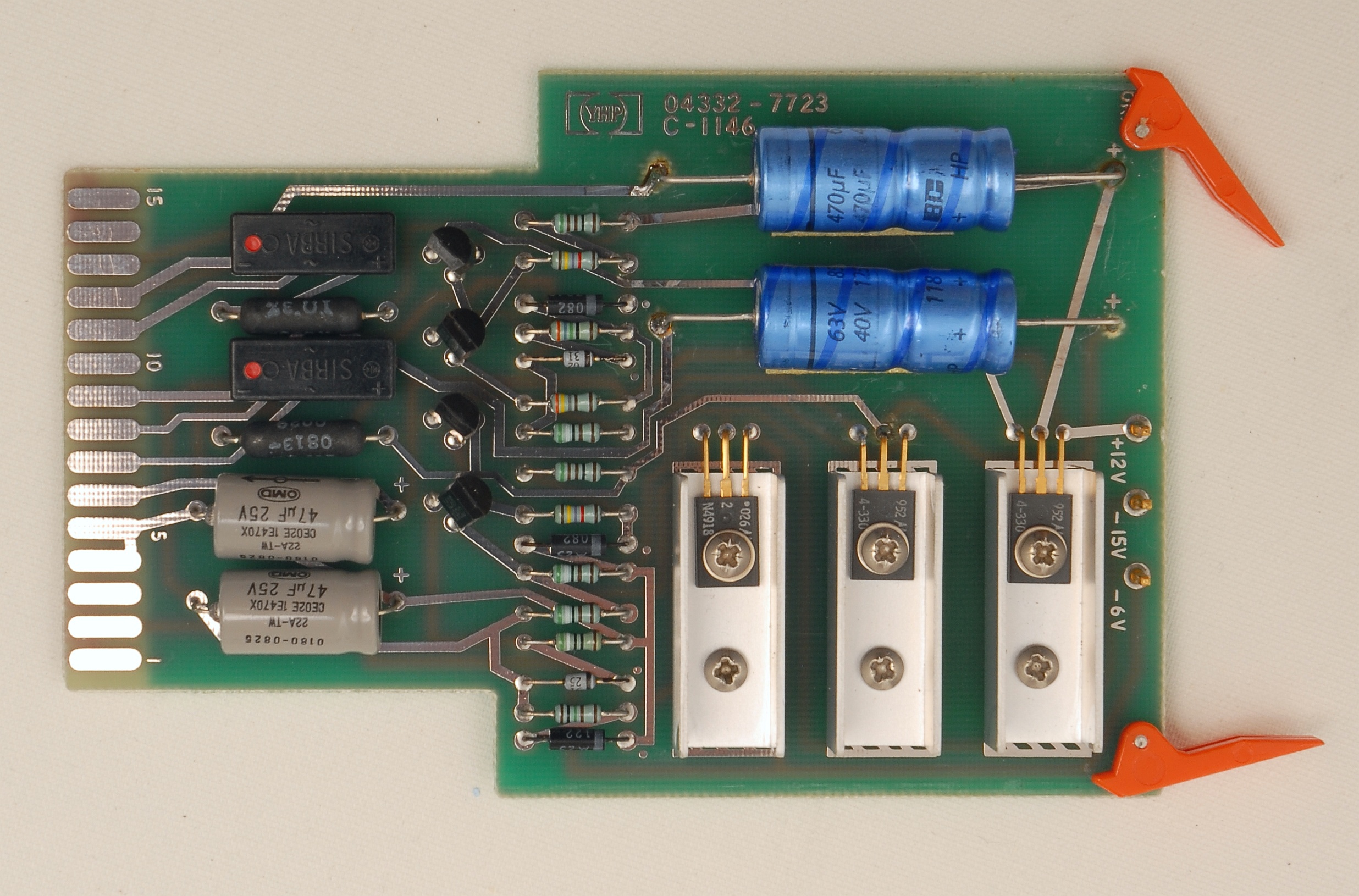
The original electrolytic capacitors on the power supply board were replaced by the previous owner, and have now been replaced again, this time with two identical, axial low-Z longlife models (see picture of A3 board below).
|
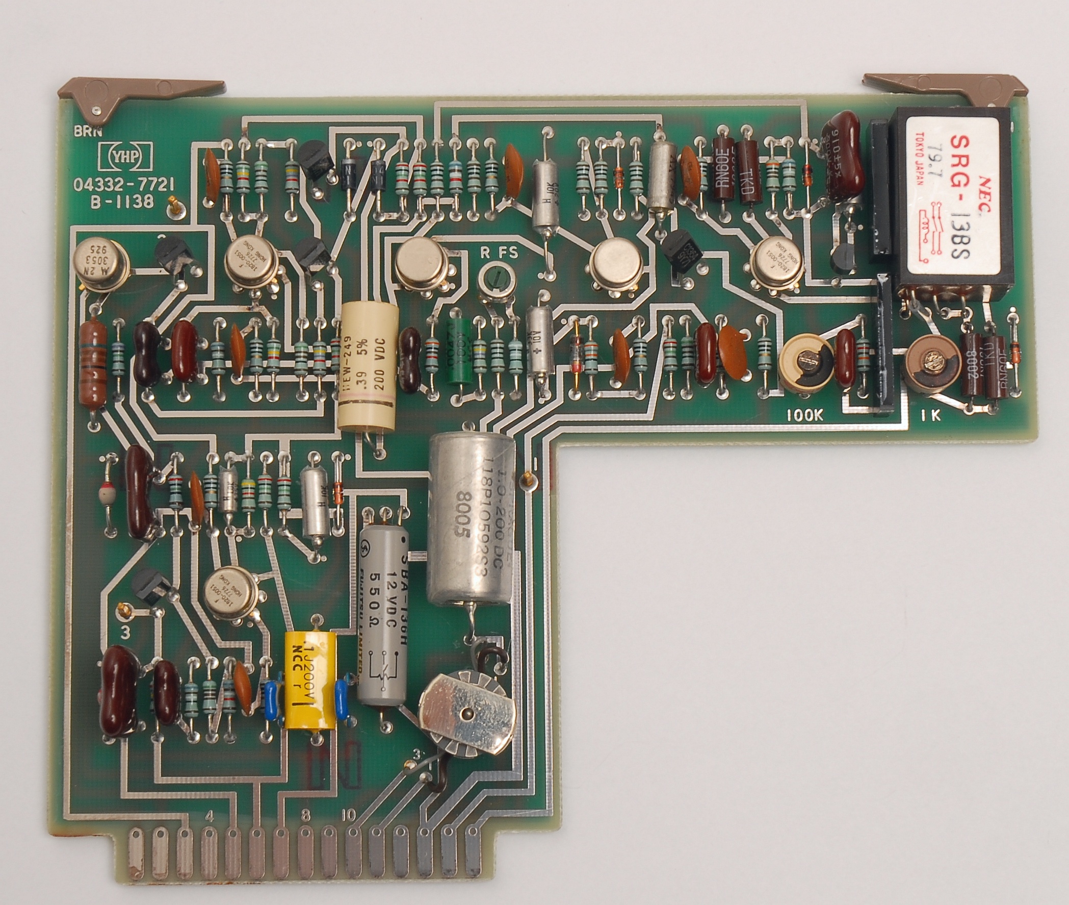
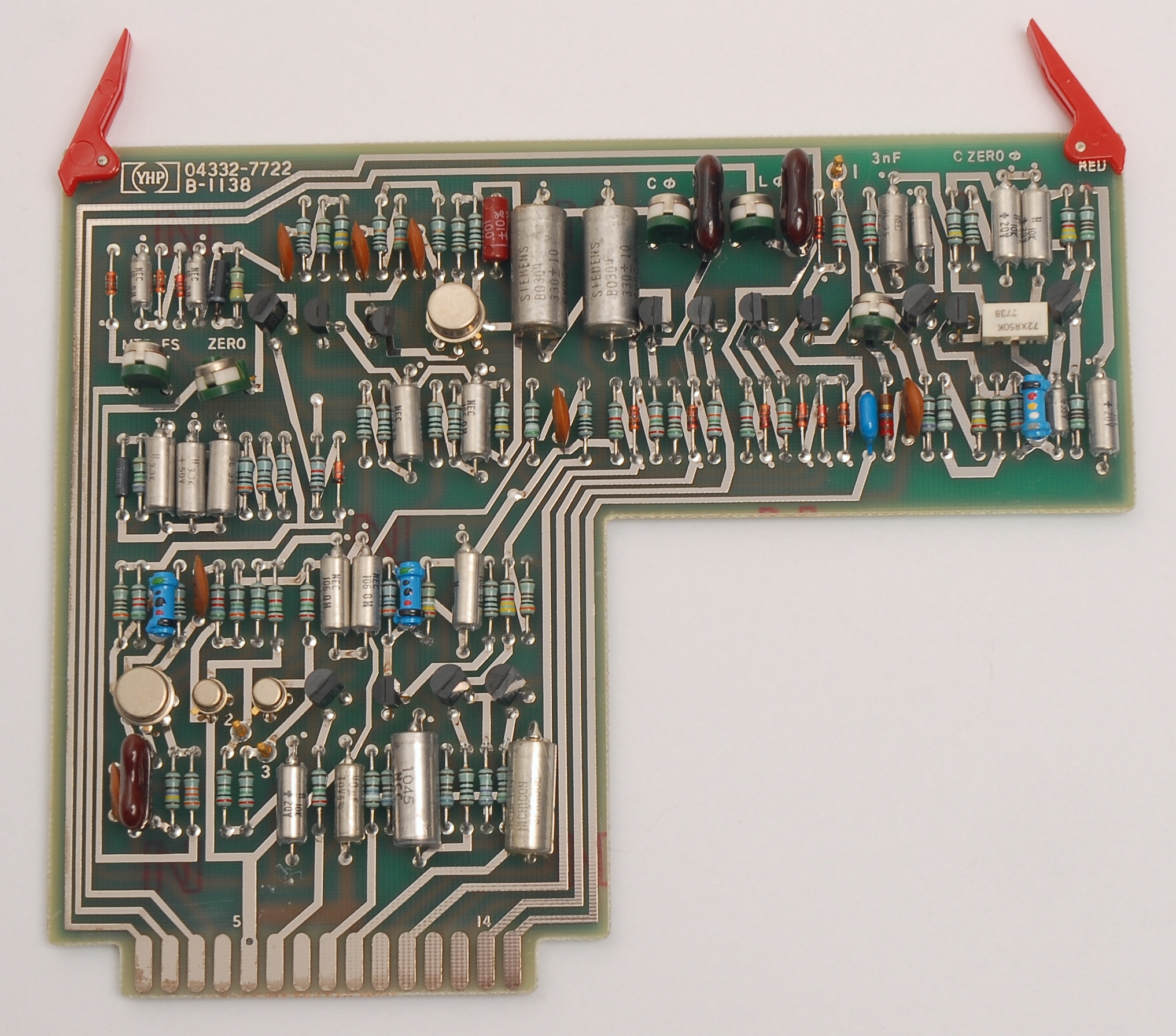
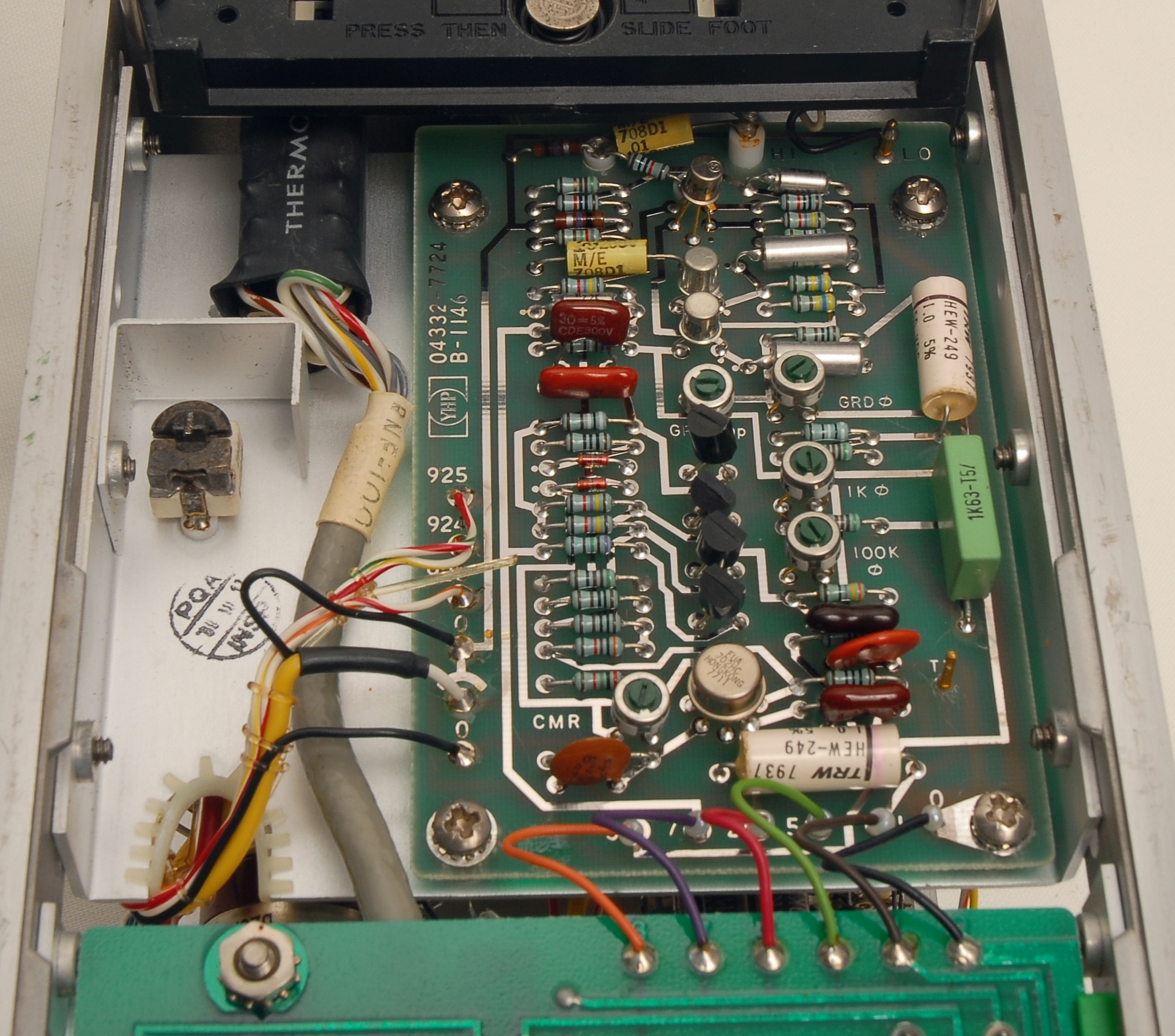
Bottom row of pictures: A closer look at the oscillator board A1 (04332-7721), the meter board A2 (04332-7722), the power supply board A3 (04332-7723) and the head amp A4 (04332-7724). The green capacitor on the right of A4 is a replacement for the original 1 µF film capacitor which had an intermittent short.
|
|
|
|
|
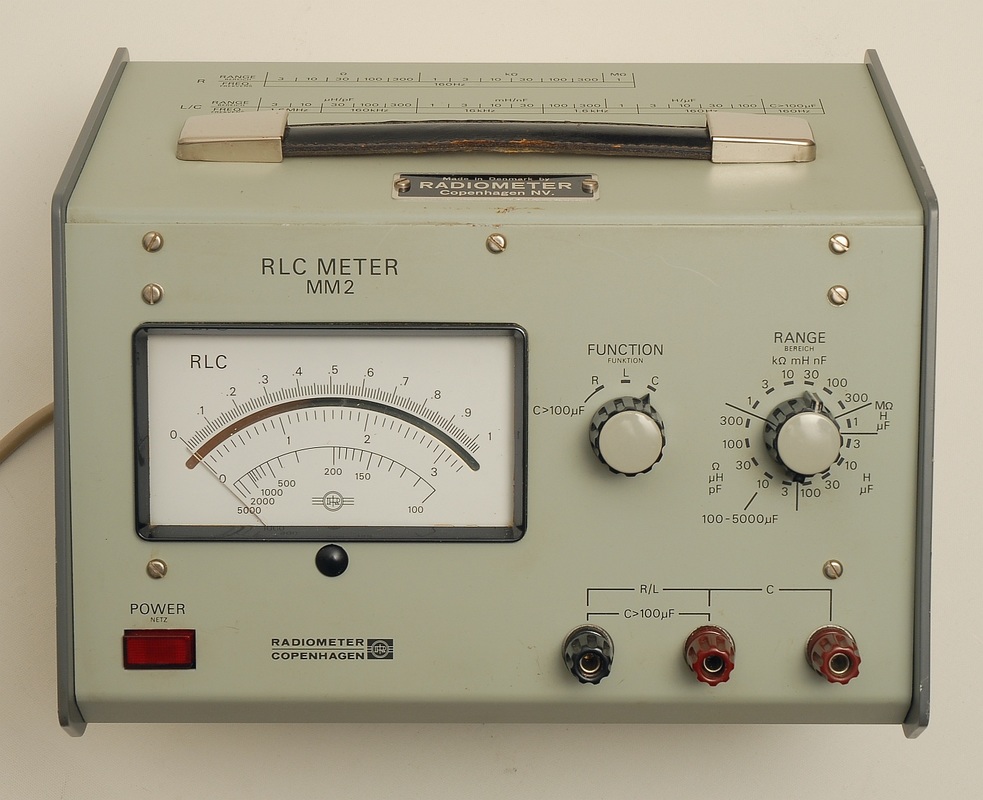
Radiometer MM2 RLC Meter
With a specified accuracy of ±2 % of reading ±1 % of scale, the MM2 is no top performer. Then again, one cannot expect miracles from a rather simple design dating back to about 1968. These days, the MM2 will typically find use as a service bench tool for quick component checks. The MM2 applies different test frequencies, from 160 Hz up to 1.6 MHz, as a means to expand its measurement range. Just like the HP 4332A the MM2 measures down to 3 µH and 3 pF full-scale, but the MM2 can measure larger values than the 4332A. Both models have an input for DC bias, highly valuable for checking capacitance diodes, for instance. One caveat, however: The MM2's test voltage for capacitors in the 3 pF through 10 µF ranges is 316 mV. This is quite high and will lead to erroneous results when measuring capacitance diodes at low DC bias voltages. The DC output of the MM2 is useful at above 150 % overrange, compared to the 110 % specified for the 4332A. On the other hand, the 4332A has two DC outputs of which one allows direct readings on a DMM for all ranges, not just those of the 1, 10, 100 sequence. A high-resolution scan of the manual with schematics for the MM2 is available at http://www.peel.dk/Radiometer/pdf/MM2.pdf |
|
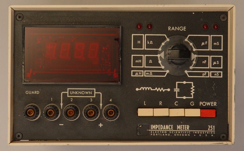
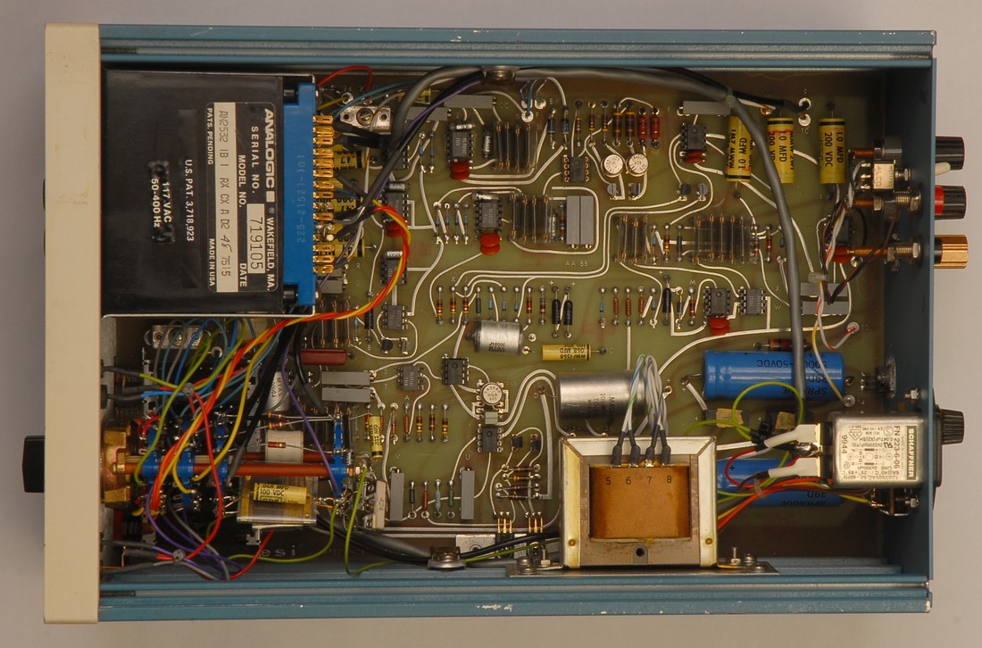
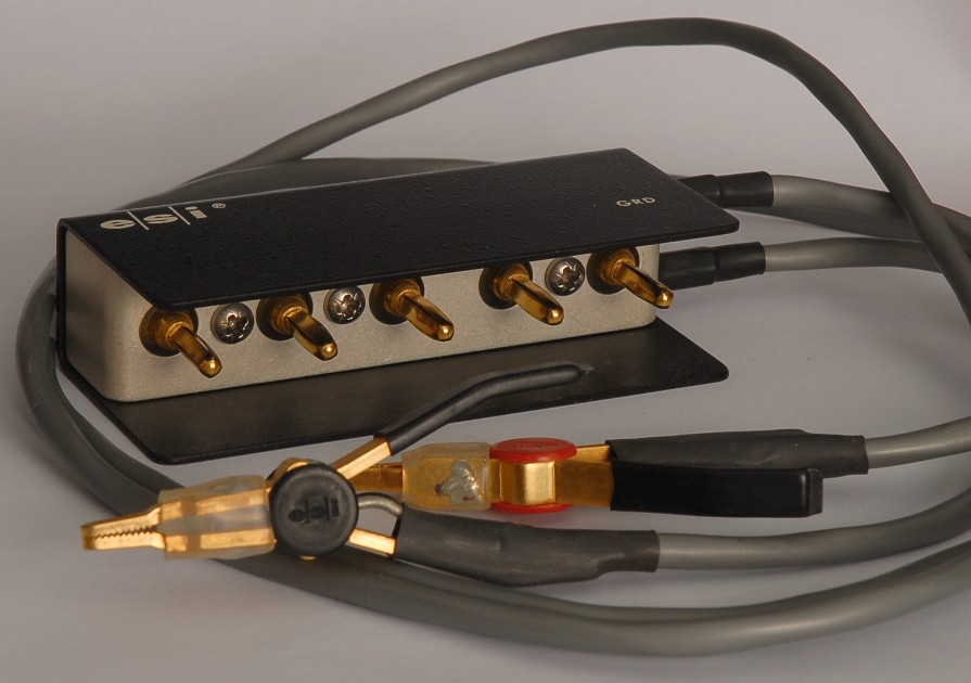
ESI 251 Impedance Meter
This is a design from about 1974 with a fixed 1 kHz test frequency, a digital display module with 1999 counts of resolution, and manual selection of ranges. The many 0.02 % wire-wound resistors in the design witness that this was meant to be a serious piece of test gear. The 251 is intended to be used with the rare model 6843 Kelvin clips (see the picture), or you may alternatively connect the component to be measured directly to the two binding posts numbered 2 and 3. The first unit I got from Ebay had various cheesy IC-sockets introduced here and there, probably in connection with a previous repair attempt. Of course this resulted in unstable measurements due to unreliable connections. The remedy was to solder ICs directly into the board, and to replace selected sockets with quality versions. Note also the red front cover, which is not the original. When capturing the voltage over time of the output on the back panel while measuring on a GenRad standard capacitor, for instance, it's evident that the ESI 251 offers a higher degree of stability than the limited resolution of the display would suggest. It may be worthwhile to improve the accuracy and stability by replacing selected operational amplifiers, by stabilizing the 1 kHz oscillator, by going through the use of trimmers, and not the least by keeping the switches clean. The instruction manual with schematics is available on the Internet is worth consulting should you decide to make any changes. Later, I got a second unit from Ebay, this time with a defective display and a fried DC output (someone likely applied bias to this output by mistake). I selected this unit for an overhaul including replacement of the 3½ digit Analogic neon display with a 4½ digit Murata LED display, a replacement of selected op-amps with newer, better models, and frequency stabilization. Check out the ESI 251 repair page. |
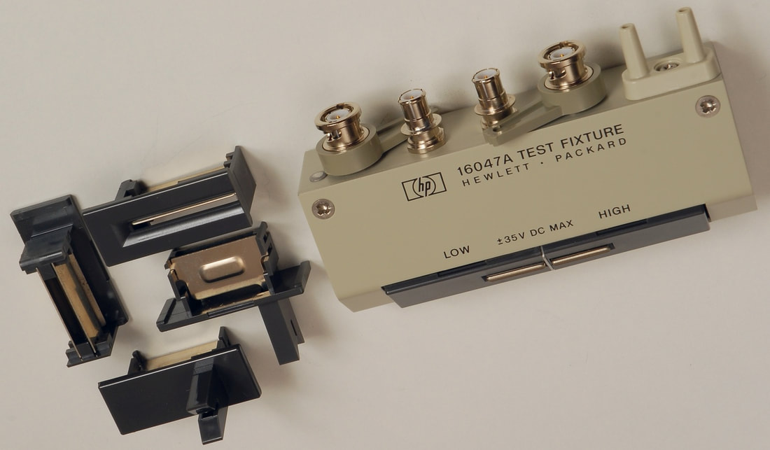
The 16047A with all three inserts. The only missing part is the shorting plate, but that can be made with only limited effort.
|
Hewlett Packard / Agilent / Keysight 16047A test fixture
When looking at the rather elevated prices on the used market for this test fixture, it seems to be very popular indeed. It is, however, not often that the 16047A is available with a full set of terminal inserts. Even worse so, many of the 16047A offered on the used market are in a terrible condition, and caution is required. Only patience (and some luck) allowed me to acquire a 16047A in pristine condition, with all the inserts, in original packaging, and at a reasonable price. The 16047A, like similar fixtures within the 160xx family, fits directly into the common layout on LCR-meters with 4 BNC connectors separated 22 mm apart. Note that there's an almost identical test fixture available, the 16047D, but this converts the 4-terminal connection into a 2-terminal configuration. This increases the useful frequency range, but at the expense of a lower suppression of contact resistance. |
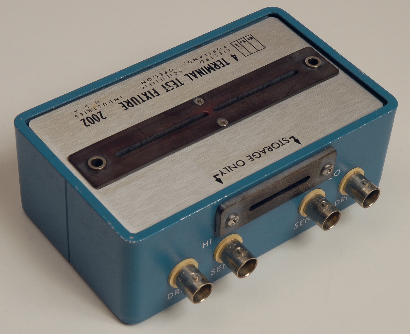
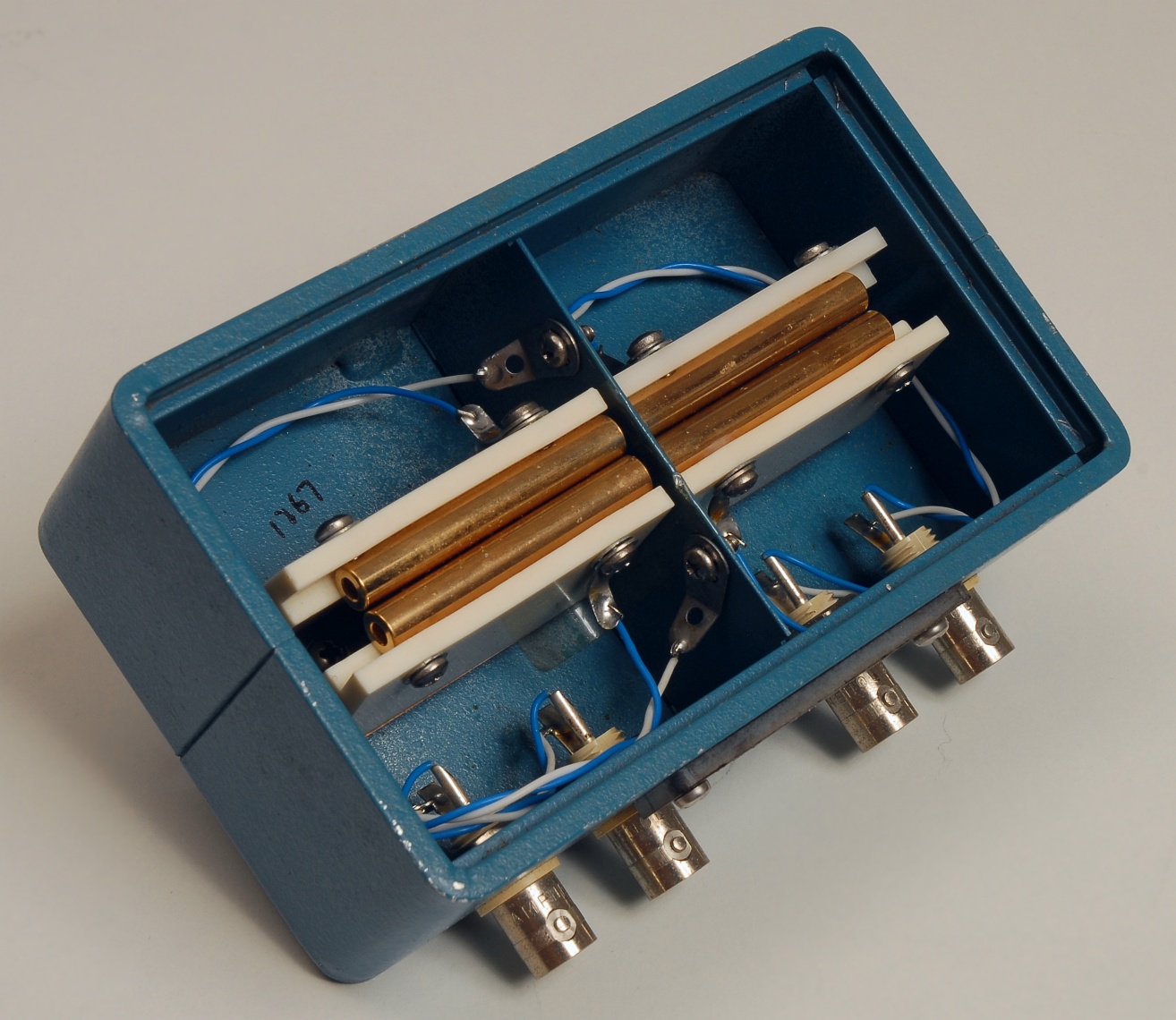
The ESI model 2002. Note how the contact terminals are made of cylindric tubes. Click on the pictures to get a closer look.
|
ESI model 2002 4-terminal test fixture
The model 2002 from Electro Scientific Industries (ESI) is seen only rarely on the used market, but is a nice alternative to other more well-known test fixtures for leaded components, such as the 16047A from Hewlett Packard / Agilent / Keysight. The terminals are made of metal tubes mounted on plastic supports that are suspended on a metal blade which then provides the contact force. This is a rather neat construction that one would be able to reproduce in a DIY project to save the often elevated costs of test fixtures. As a detail, the 2002 includes a small storage compartment for a short. The disadvantage of the ESI 2002 is that the terminal pairs are located rather deep inside the box so that component leads with at least 10 mm length are required to make contact. Note that the model 2002 is not made to fit directly into the common layout on LCR-meters with 4 BNC connectors separated 22 mm apart, but must be used with cabling. |
|
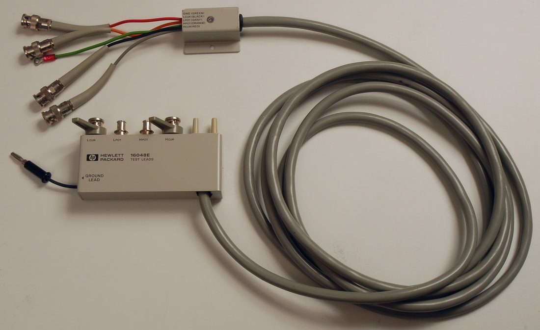
Hewlett Packard / Agilent / Keysight 16048E test leads
In some test setups the test fixture cannot be located directly to the LCR meter, like on a production line or when using an oven for characterizing the temperature dependencies of components. In such cases an extension cord is required. The 16048A is an example of a ready-made extension cable to be used with 4-terminal systems. The 16048E has a length of 4 m. Shorter versions are the 16048A (1 m) and the 16048D (2 m). The 16048E is delivered with a BNC bracket (part no. 16032-60001) with four BNC to produce the 4-terminal configuration at the end of the test leads. You can easily make a similar bracket from a sheet of metal and four BNC connectors, but don't forget the metal screen separating the High and Low pairs. As a cheaper alternative, one could use four standard BNC cables. However, the GND connection of the 16048E is connected to the metal boxes and to a braided screen covering the four coaxial cables inside the thick lead. To have a similar screening you need to pull the four BNC cables through a braid, and then protect it all with heat shrinking tubing, for instance. The 16048E saves you from going through this hassle. |
|
Hewlett Packard 4800A Vector Impedance Meter
The advantages of this rather old piece of instrument are its wide frequency range from 5 Hz through 500 kHz, and that it allows the user to see results immediately when fiddling with the frequency, which is rather useful when testing eg. resonant components. I can be a bit tedious cranking the frequency dial up and down when switching between frequency ranges, but it only requires some patience. I found that the usefulness of the instrument was highly strenghtened when I connected a frequency counter to the frequency monitor output, and I will highly recommend this if you are measuring resonances of coils, for instance. The instrument features analog outputs which give voltages proportional to the impedance magnitude and phase, and by connecting a pair of multimeters it can help documenting your measurements, but do not expect stellar measurement accuracy. |
|
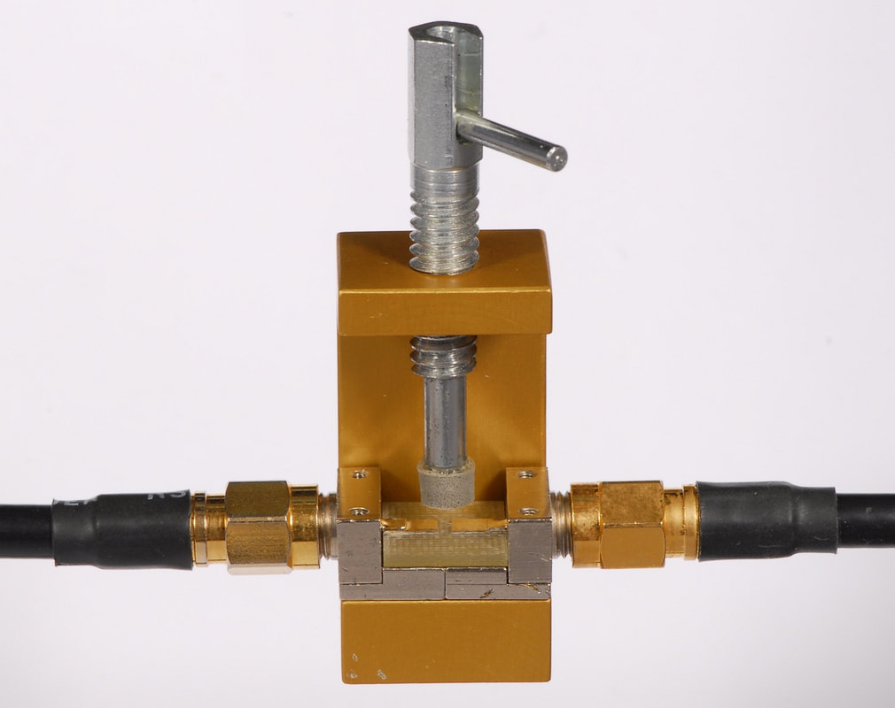
Coilcraft test fixtures
Not only the manufacturers of LCR meters and impedance analyzers offer test fixtures for testing components. Coilcraft, one of the leading manufacturers of inductive passives, offers some interesting test fixtures. Unfortunately, these test fixtures surface only rarely on the market for used test gear. The SMD-A fixture (upper picture) is made for 1-port analyzers with APC-7 connector interface, such as the HP 4291A, 4291B, etc. Just like the SMD-D fixture, the SMD-A fixture accommodates SMD size 0603 through 1812. The SMD-D fixture (lower pictrure) is a 2-port test fixture with SMA connectors made for testing size 0603 through 1812 SMD components by using a network analyzer. The center rod is spring-loaded and equipped with a foam pad. |
