Repairing the HP 4271A 1 MHz Digital LCR Meter
|
I acquired an old HP 4271A that was in a well-preserved shape, but it had one serious issue: It produced some rather unreliable figures. The prospects of owning a 1 MHz LCR meter, albeit a quite old one, that could actually be of value for checking ceramic capacitors, for instance, convinced me that I should try to fix it.
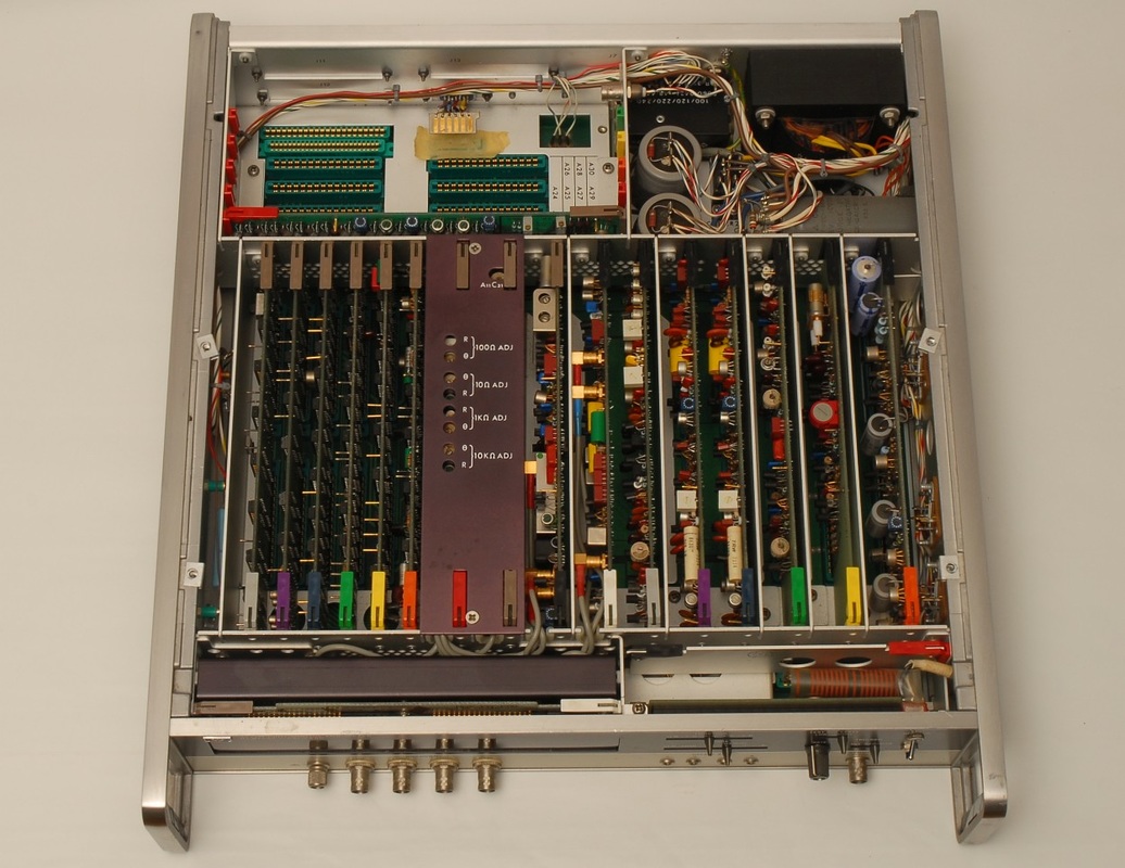
The service manual is essential to debug the 4271A. The design is rather convoluted with control signals going back and forth between the modules with very limited means for intervention that could help isolating errors. An understanding of the measurement principle with the two sets of cycles for capacitance/inductance and for admittance/resistance is important, and the timing diagram in the manual is a help. Another helpful item would be the extender board, but this was missing in the unit I acquired. |
|
|
The slideshow demonstrates how the 4271A cycled between results when measuring a 1 kOhm resistor. Note how a fraction of 10 seems to be in play and how the values of the capacitance and the resistance appear to add up to a count close to 10000, putting the decimal point aside.
In this case the measurement range was selected manually to 2. By changing measurement range or the value of the component to be measured the pattern would change. Depending on the combination of setting and component value the pattern could even come to a halt, but not necessarily with the correct result. The signal flow of the 4271A makes it challenging to distinguish between cause and effect. By inspecting the signals at various test points it was clear that the analog circuitry worked as intended. The issue appeared to be related to the timing of the measurement cycles. Inspection and deduction eventually pointed me to the counter board A18, and a logic analyzer HP 1660A came in handy. In the slideshow test pins from the logic analyzer probe the counter U11 on board A18. |
|
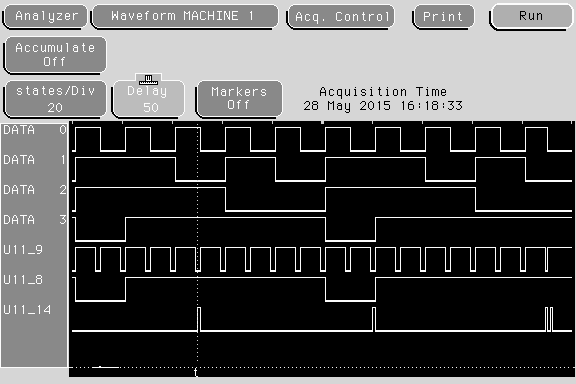
This screendump from the 1660A logic analyzer reveals what's wrong: The counter U11 receives a reset pulse, but in fact never gets reset. It continues the count totally unaffected. This corrupts the counting protocol of the 4271A so that counts propagate into the following cycle, and cycles are shortened. The U11 is the last counter IC in the chain of BCD counters on board A18 which explains the size of the observed steps. A similar error in the first IC in the chain of counters, for instance, would have appeared as noisy measurements and would have been more difficult to trace.
The screen dump is a state waveform with clock from U9 pin 9. On pin 14 we find the reset pulse, which should leave the 4 data pins in state '1111'. However, for U11, this does not happen. Note that the outputs of the ICs in the BCD counter chain have inverted polarity, so a pattern of '1111' equals a zero count. |
Conclusion: The culprit was the U11 on board A18, a blanking decade counter from HP with stock no. 1820-0119. There seems to be no direct replacement for this IC, and I considered to replace it with a small CPLD on an adapter DIL board. Eventually, compelled by an urge to keep as much of the original design as possible, I decided to go with an original, old stock IC I found at one of the retailers on the net.
