Repairing the Ballantine 323 RMS meter -- Unit 1
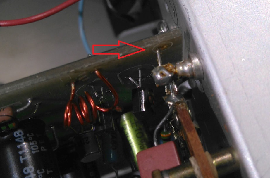
A broken ground connection, likely due to mechanical stress.
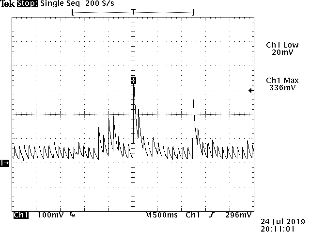
When disassembled, the 323 gladly picks up RF signals which results in a varying offset and occasional meter movements. The figure above shows a detected WiFi signal, with the filter capacitors removed, seen at the U102 output. Unfortunately with the filter capacitors in place, and in assembled condition, the 323 remains very sensitive to RF interference.
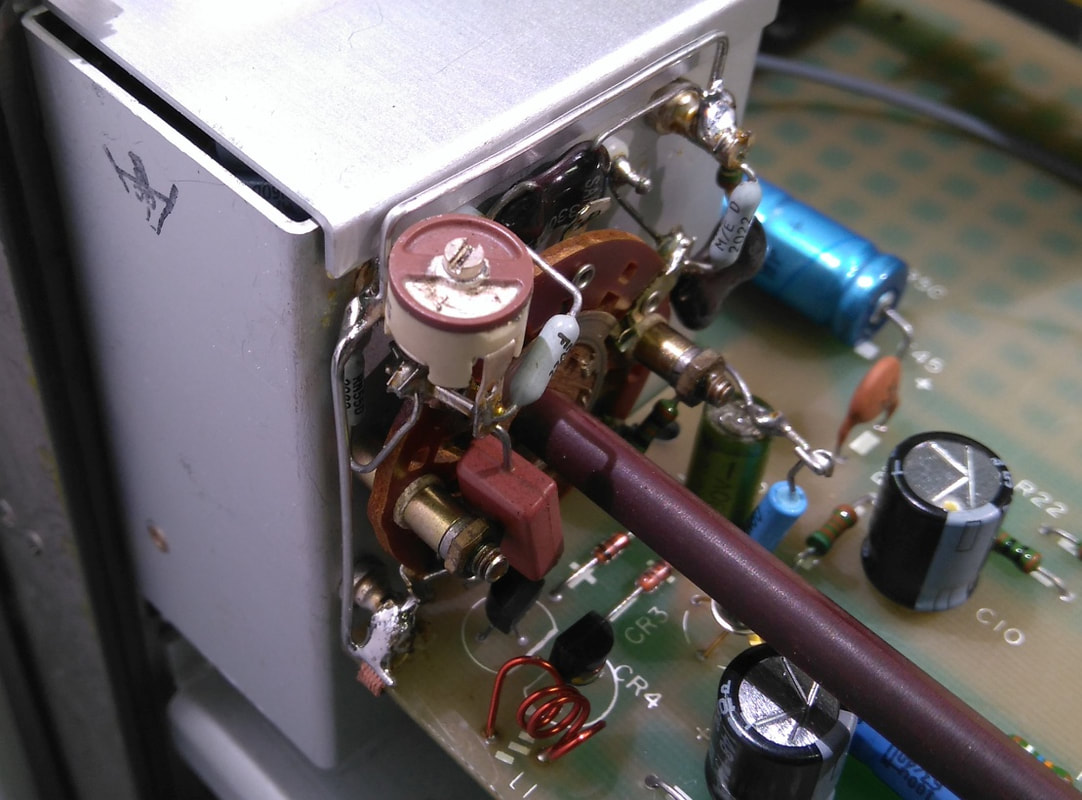
The three standoffs riveted into the shielded attenuator box had to be connected with a wire to ground.
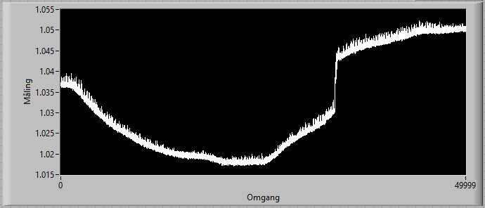
The measurement session of a 1 V source (Fluke 510A + Gertsch RT-60 IVD) reveal some rather large changes. Ballantine specifies a typical temperature coefficient of 0.1%/°C. In the graph above we encounter a change of 0.67 %/°C, even with squareroot applied to the measured voltage. Quite a disappointing result. If the diodes were indeed changed in the past, this could explain some of the temperature dependency.
|
I acquired a Ballantine 323 which had an issue with an offset wandering nervously around the scale, and with meter needle pegging violently when operating the instrument. The usual contact cleaning removed some of the issues with a pegging needle, but much more had to be done.
The instrument is a version with a pair of Schottky-diodes and ICL7650 chopper amplifiers. When examining the instrument closer I found to my surprise that there were no resistors connected between the non-inverting inputs of the chopper amplifiers and GND to allow a flow of the input bias currents. The time constants and the capacitors used for the averaging filter suggest that there should be a resistor of around 2.5 MOhm from each Schottky diode to GND, but there was none, and nothing suggested that there has ever been any. The schematics available on the net apply to the old version of the 323 which uses backwards diodes in another configuration, so no help on what the designers might have intended. In any case, I decided to add a 3.3 MOhm resistor in from each of the two schottky diodes to GND, and as a result, the offset was significantly reduced. Note that the input bias current of the ICL7650 is not that well specified, and ideally, the ICL7650 should be replaced with the improved ICL7650S, which has specified a maximum input bias, and the resistor should then be chosen accordingly. After the addition of the resistors there was still some varying offset, and it seemed to depend on the handling of the instrument. A closer examination revealed a broken connection between the ground of the input attenuator, as shown in the picture on the left. To ensure a proper (and flexible) connection I soldered a piece of desoldering braid from the amplifier board to the attenuator ground standoff. Furthermore, large areas of the boards around the screws that should ensure proper grounding between the boards have a layer of lacquer, and the dented spacers used may, or may not, provide the required connection. To ensure a proper connection I soldered a piece of desoldering braid from the amplifier board to the attenuator ground, and another piece from the rear board to the amplifier board. The improved grounding helped somewhat on the changing offset, but still, the offset varied slightly and would occasionally rise. To make things even more odd, the actual orientation of the instrument had an influence on the offset. This was also the case when I tried to power off the preamplifier. Adding all this together, I started to suspect that the instrument in its disassembled condition had an issue with RF injection at the test bench. And behold, by removing the filter capacitors a rectified WiFi signal becomes clear to see. Turning off the wireless router on the wall magically removed these spikes. The lesson is that this kind of detector with its combination of low level and wide bandwidth calls for a proper RF design, even when the meter is designed for much lower frequencies. The capacitors for the averaging filter do not help suppressing the unwanted RF rectification of the WiFi signal as the filter arrangement has no effect at the frequencies involved. The averaging filter only makes the rectified WiFi signal move more slowly. The box covering the diodes have limited effect as several tracks and wires are still exposed and act like an antenna. Ballantine placed one ferrite bead close to each diode, likely as an attempt to suppress the effect of RF injection, but I doubt this has any real effect due to the high impedance level. Ideally, the Schottky diodes and the chopper amplifier stage should have been co-located under a shielding box, and feed-through capacitors and an improved, EMC-robust board layout would be something to consider. The way the 323 is designed, it depends way too much on the RF isolation of the instrument casing. I also noticed that the capacitors C112 and C113 were placed from the inverting input of each ICL7650 amplifier to ground. This really looks like a blunder, as capacitors placed in this way are an invitation to unstability, and in the best case, they will result in an unwanted amplification of high frequencies. The capacitors were moved so that they now are in parallel with the feedback resistors R102 and R121 (going from the output to the inverting input). Having assembled the 323 I found that the ranges were not scaling properly: The 10 V through the 300 V ranges showed too high a value, and the other ranges too small a value. The reason was that the three standoffs riveted into the attenuator shield box were not connecting properly. A wire connecting all three to ground did the job. After all this, the 323 was not able to provide full 1 V on its DC output, and I had to increase the gain in the chopper amplifier stage. The reason for this could be that the Schottky diodes were indeed replaced in the past. Finally, when logging the DC-output for a 1 V signal, some weirdly looking spikes appeared with 2 minutes interval. I had located the 323 further away from the wireless router on the wall, but instead, the 323 was now closer to a PC. Sure enough, the spikes almost vanished when I placed a sheet of metal between the PC and the 323. Clearly, this 323 has a serious issue with EMC, and I sincerely hope Ballantine has has made efforts to make the latest 323 models more robust. The graph on the left shows the output from the 323 at 1 V input, while the 323 was located 1 m away from the PC. The WiFi signals are still evident, though. The following sums up the rest of the changes made: IC sockets replaced with more reliable models Electrolytic capacitors replaced with low-Z high-temperature models To follow: The chopper amplifiers ICL7650CPD should be replaced with Renesas ICL7650SCPDZ (Farnell 2111966) which is an improved version of the ICL7650 with a lower bias current of max. 10 pA. |
Repairing the Ballantine 323 RMS meter -- Unit 2
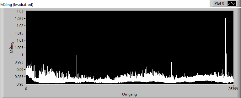
The square-rooted output voltage af the 323, for a 1 V input, over 24h, with the filtering time constant set to "0.25 s", showing spikes from Wi-Fi activity.
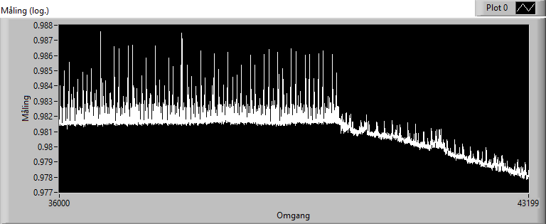
So, shielding definitely has an effect. The moment in time when the 323 is being wrapped in tin foil is clear to see. The graph shows the square root of the output voltage over 2 hours.
|
Driven by the observations above and the eager to find out if the Schottky diodes had been replaced, or if the drift performance was indeed representative, I found another Ballantine 323 of what seemed to be the same version. Another reason was that I needed an instrument I could dedicate to some power supply noise measurements.
Despite the same appearance on the outside, it turned out that the second unit was a version with uni-tunnel diodes, mechanical chopper, and AC-amplifier. Though annoyed by the fact that I could then not find out more about the Schottky diodes used in the first unit, I realized there was something to learn from having two different implementations of the 323 at hand. Remarkably, the unit worked well at 110 V, but flipping the internal voltage selector to the "240 V" position made the unit burn the fuse while turning up the voltage through a variac. I discovered that two of the transformer's wires had been swapped, so in the "240 V" position, one 110 V section of the transformer was connected directly to the mains, while the other section was shorted! In the "120 V" position the wrong wiring had no effect as the two 110 V sections were in parallel as intended. Conclusion: Ballantine had obviously never tested this unit in its "240 V" position, and the question is how many units were produced with this wiring error. After the re-wiring of the transformer, and the mandatory rinse of the rotary switches with a contact cleaner, the 323 seemed to work quite well. The mechanical chopper emits a gentle buzz, which to only some may be annoying at a quite location. The needle pegs when changing the filtering, and when powered on, and perhaps more than observed for the unit 1 above. In any case, this 323 did a fine job of measuring power supply noise. I realized that this instrument and the first instrument have one thing in common: They are both sensitive to electromagnetic interference. In a lab where WiFi is present close to the meter, some reading deviation should be expected. This need not be an issue, however, as the instrument is not intended for accurate measurements. It is still very useful for measuring power supply noise or for adjusting RF circuits due to the analog meter. The upper figure on the left shows the square root of the voltage on the output of the 323 over 24 hours, starting about ½ hour after power-on. The Wi-Fi activity is clearly visible. The huge burst coincides with a laptop synchronizing to OneDrive. The lower figure shows the effect of wrapping the 323 in tin foil during the measurements. The noise is reduced, though not gone, and the output starts to drift due to the rise in temperature. |
