OCXF
In some frequency reference designs crystal filters are used, either in the front-end of an off-air receiver or perhaps as a post filter to reduce out-of-band noise. If at all possible, one would prefer to get rid of the bulky, delicate and hard-to-find crystals and go for digital processing, but situations appear where they are retrieved from obscurity. For demanding applications you may not assume that such crystal filters are perfect and do not change. The transfer phase will change with the temperature, and so will the apparent phase of the signal you try to track with your off-air receiver, or of the signal you are filtering. Should a DCF77 signal at 77.5 kHz be shifted 30 degrees over 24 hours, for instance, it will correspond to a frequency shift about 1.2 * 10e-11. If you aim to get below the 1*10e-12 mark over 24 hours the phase change of any device before the off-air receiver should be kept below 2 degrees. A similar requirement will apply to a post-filter connected to the output of a frequency reference. This is also something to keep in mind when it comes to a ferrite rod antenna; Too high a Q may result in diurnal phase variations with temperature. If you have a design that incorporates crystal filters, be sure to know how they behave. The cuts for low-frequency crystals will typically result in rather large phase shifts over the operational temperature range, and that brought me to the idea of testing oven heating of crystal filters for my experiment DCF77 receiver.
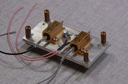
This is the thermal block that acts as base for the two 77.5 kHz crystals. The crystals are mounted on the other side. In the middle you find the NTC resistor (Siemens/Epcos 47k type K45, ordering code B57045K0473K000).
The response of one crystal filter section, measured with HP 3577B with Z3805A as reference, after trimming for center frequency and for best symmetry. Span is 10 Hz, and there's 1 dB per division.
|
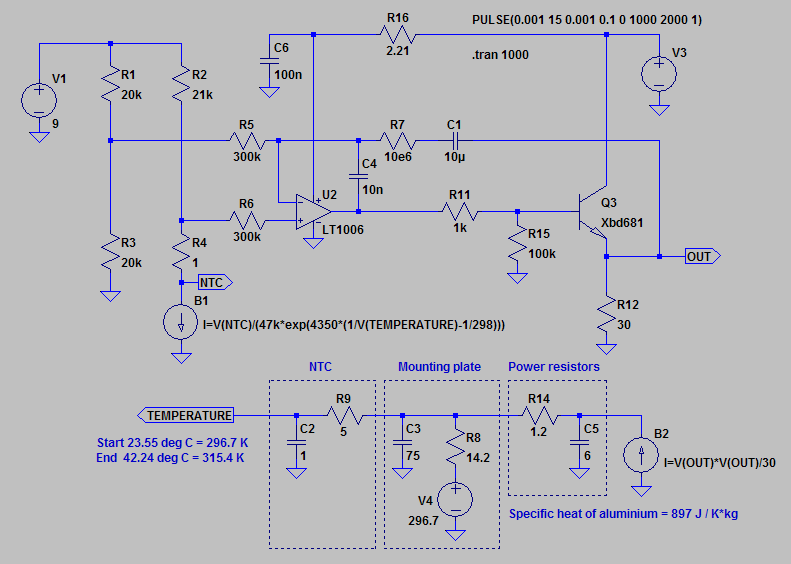
In order to model the behavior and to select proper component values a simulation was carried out in LTSpice. The subcircuit declaration for the BD681 NPN Darlington power transistor is located outside the picture. The resistor R2 is adjusted to get the wanted temperature.
The capacitors in the mechanical model represent the heat capacity, and the value is found by mutiplying the weight of the object with the specific heat of the material it's made of, in this case aluminium. The simple mechanical model used here includes the power resistors, the mounting plate for the crystals, and the NTC resistor. A more elaborate model would include the crystals, the mounting arrangement of the mounting plate inside the diecast box the filter is intended for, etc. The voltage generator V4 represents the ambient temperature, and the current generator B2 represents the power applied to the heater resistors. The resistors in the mechanical model represent the heat resistance; R14 from the power resistors to the mounting plate, R9 from the mounting plate to the NTC resistor. The heat resistance R8 for the mounting plate to the surroundings is estimated from consulting tables. |
|
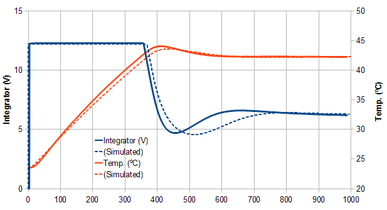
The graph shows the temperature (orange, right scale) and the heater voltage (blue, left scale) for 1,000 seconds after applying power to the regulator, with the bridge resistors set for a temperature about 42 ºC. The start temperature was 23.5 ºC. The dotted lines show the result of the simulation. The overshoot is quite acceptable for this purpose.
The temperature was measured with my AOIP PN5207 thermometer with the thermocouple located between the two crystals. The heater voltage and the voltage from the thermometer were acquired by the NI USB-6251 Multifunction DAQ. |
|
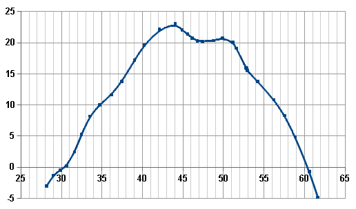
This is the phase of the first of the two crystal filter sections as a function of the temperature in ºC. A 10-turn trimmer resistor was added to the bridge (R2 in the Spice model), and for each change of setting the phase was measured with an HP 3577B network analyzer, but only after 10 min. of waiting to allow the temperature to fully settle.
The response, which to some degree appears to be parabolic, includes a couple of turning points, of which I picked the one around 47 - 48 ºC. Once the working temperature was selected, the trimmer resistor, being notoriously unreliable, was replaced with a fixed resistor. |
